Table of Contents
Advertisement
Quick Links
Advertisement
Table of Contents

Subscribe to Our Youtube Channel
Related Manuals for Julabo HT60-M3


Summary of Contents for Julabo HT60-M3
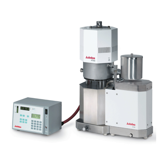
- Page 1 Operating Manual High Temperature Circulator HT60-M2 HT60-M3 C.U.-cooling unit Forte HT with cooling unit 1.950.3727.us.V05 06/21 JULABO USA, Inc. 884 Marcon Boulevard Allentown, PA 18109 Phone: +1(610) 231-0250 Fax: +1(610) 231-0260 info@ julabo.us www.julabo.us...
- Page 2 Congratulations! You have made an excellent choice. JULABO thanks you for the trust you have placed in us. This operating manual has been designed to help you gain an understanding of the operation and possible applications of our circulators. For optimal utilization of all functions, we recommend that you thoroughly study this manual prior to beginning operation.
-
Page 3: Table Of Contents
HT60-M2 / HT60-M3 TABLE OF CONTENTS OPERATING MANUAL ......................... 5 INTENDED USE ..........................5 1.1. Description ........................5 OPERATOR RESPONSIBILITY – SAFETY INSTRUCTIONS ............. 6 2.1. Disposal ..........................7 2.2. Technical specifications....................8 2.3. Cooling water connection ....................11 OPERATING CONTROLS AND FUNCTIONAL ELEMENTS ............. 12 M2 or M3 –... - Page 4 TROUBLESHOOTING GUIDE / ERROR MESSAGES .............. 55 10. ELECTRICAL CONNECTIONS....................57 11. REMOTE CONTROL ........................59 11.1. Setup for remote control ....................59 11.2. Communication with a PC or a superordinated data system ......... 60 11.3. List of commands ......................61 11.4.
-
Page 5: Operating Manual
Operating manual Intended use The High Temperature Circulators HT60-M2 and HT60-M3 are to be employed especially for closed tempering circuits in the laboratory, the technical institution or the production, like e.g. for distillation plants, reaction vessels, autoclaves, injection moulding tools. -
Page 6: Operator Responsibility - Safety Instructions
Operator responsibility – Safety instructions Operator responsibility – Safety instructions The products of JULABO ensure safe operation when installed, operated, and maintained according to common safety regulations. This section explains the potential dangers that may arise when operating the circulator and also specifies the most important safety precautions to preclude these dangers as far as possible. -
Page 7: Disposal
Colors: yellow, black Hot surface warning. (The label is put on by JULABO) Observe the instructions in the manuals for instruments of a different make that you connect to the circulator, particularly the corresponding safety instructions. Also observe the pin assignment of plugs and technical specifications of the products. -
Page 8: Technical Specifications
Operator responsibility – Safety instructions 2.2. Technical specifications HT60-M2 HT60-M2 & C.U. Working temperature range °C 70 ... 400 40 … 400 Temperature stability external °C ±0,01 ... ±0.1 Display accuracy ±0.5 ±1Digit Temperature selection digital via keypad indication on LCD DIALOG-DISPLAY (°C/°F) remote control via PC indication on monitor Temperature indication... - Page 9 HT60-M2 / HT60-M3 HT60-M3 HT60-M3 & C.U. Working temperature range °C 70 ... 400 40 … 400 Temperature stability external °C ±0,01 ... ±0.1 Display accuracy ±0.5 ±1Digit Temperature selection digital via keypad indication on LCD DIALOG-DISPLAY (°C/°F) remote control via PC...
- Page 10 Operator responsibility – Safety instructions Electrical connections: Computer interface RS232 or RS485 or Profi Programmer input 0 - 10 V / 0 - 20 mA Temperatur recorder outputs Channel 1 / 2 0 - 10 V / Channel 3 0 - 20 mA / 4 - 20 mA Stand-by input External alarm device Switching capacity max.
-
Page 11: Cooling Water Connection
HT60-M2 / HT60-M3 2.3. Cooling water connection Cooling water pressure (IN / OUT ) max. 4.5 bar Difference pressure (IN - OUT ) 2.0 to 4.5 bar Rate of flow typical 2 l/min Recommended cooling water temperature range: 10-15 °C Permissible cooling water temperature range: 5-35 °C... -
Page 12: Operating Controls And Functional Elements
Operating controls and functional elements Operating controls and functional elements M2 or M3 – control electronic Mains power switch, illuminated Start / stop key Working temperature T Key for automatic filling and aeration High temperature warning limit Low temperature warning limit Safety temperature Adjustable excess temperature protection (safety temperature) Control type: internal/external control... - Page 13 HT60-M2 / HT60-M3 MULTI-DISPLAY (LED) temperature indication Display of internal/external actual value Indicator lights: Temperature indication - external actual value Alarm / Cooling / Heating DIALOG-DISPLAY (LCD) for indication of: Line 1: Setpoint Line 2: Internal or external actual value...
- Page 14 Operating controls and functional elements Rear view SERIAL REG+E-PROG STAND-BY ALARM HT60 MADE IN GERMANY Interface RS232/RS485 SERIAL Programmer input and temperature recorder output REG+E-PROG Stand-by input (for external emergency switch-off) STAND-BY Alarm output (for external alarm signal) ALARM Control exit Connector for control cable of circulator HT60 M2 –...
-
Page 15: Ht60 High Temperature Circulator With C.u.-Cooling Unit (Option)
HT60-M2 / HT60-M3 HT60 High Temperature Circulator with C.U.-cooling unit (option) Front view: Cold zone Cooling zone Heating zone Rear view: Presentation: Cooling unit divided from HT60... - Page 16 Operating controls and functional elements Stand rod attachment with mouting screw; 12; M8 Connector for second expansion vessel; M16x1 / 37° Drain plug for bath liquid; M16x1 43/43a Expansion vessel / Connector for expansion vessel; M16x1 (When filling it serves as funnel) 44/45 Cooling water connectors at the HT60, M12 / 37°...
-
Page 17: Safety Notes For The User
HT60-M2 / HT60-M3 Safety notes for the user 4.1. Explanation of safety notes In addition to the safety warnings listed above, warnings are posted throughout the manual. These warnings are designated by an exclamation mark inside an equilateral triangle. “Warning of a dangerous situation (Attention! Please follow the documentation).”... - Page 18 Safety notes for the user Employ suitable connecting tubing. Avoid sharp bends in the tubing, and maintain a sufficient distance from surrounding walls. Make sure that the tubing is securely attached. Regularly check the tubing for material defects (e.g. for cracks). Never operate damaged or leaking equipment.
- Page 19 HT60-M2 / HT60-M3 Notice: Check the safety installations at least twice a year! Excess temperature protection according to IEC 61010-2-010 With a screw driver turn back the adjustable excess temperature protection until the shut- down point (actual temperature). Low level protection To check the function of the float of this unit it cannot be operated manually.
-
Page 20: Preparations
Place the unit in an vertical position. A wall distance of at least 15 cm must be maintained for ventilation, allowing internal heat to be conducted away from the unit. JULABO Order-No. 9790100 C.U. cooling unit M2 or M3 remote control electronics: The unit should be set up at a dry location. -
Page 21: Installation
HT60-M2 / HT60-M3 5.2. Installation Caution: Installation of the C.U.-unit / Installation of the magnetic valve Always turn off the unit and disconnect the mains cable (38) from the power source before installing the unit. The control cable with plug (56) of the C.U.-cooling unit or the magnetic valve always have to be connected or disconnected in absence of current. - Page 22 Preparations Installation of the magnetic valve JULABO Order-No. 8 980 704 3 Magnetic valve Fix the expansion tank (43) to the connection (41) (open end wrench SW19) Screw the magnetic valve to the entry for cooling water (45). Respect the flow direction (arrow) Connect the cooling water to the magnetic valve and to the outflow of cooling water (44) by means of tubes 8 mm ID.
- Page 23 HT60-M2 / HT60-M3 5.3. Inert gas superimposition Warning: Gas leakage Danger of asphyxiation Due to the system design, the cooling zone of circulator is not hermetically sealed since the cooling zone is also used as an expansion vessel for the expanding heat carrier medium in heating mode.
-
Page 24: Bath Fluids
Fire or other dangers when using bath fluids that are not recommended: Please contact JULABO before using other than recommended bath liquids. JULABO assumes no liability for damage caused by the selection of an unsuitable bath fluid. Unsuitable bath fluids are fluids which, e.g.,... -
Page 25: Tubing
Danger of explosion Burning of people’s skin Difficulties in breathing due to hot atmosphere JULABO supplies the metal tubes with assembly instructions (No. 1.950.0013). There all the instruction for assembly are indicated. They absolutely have to be respected. Safety recommendations Employ suitable connecting tubing. -
Page 26: Power Connection
1. Connect control cable (55) with control exit (35) of the control electronics M2 / M3 and latch the saftey loop. Lengthening piece for control cable, 5 m - JULABO Order-No. 8 980 125 2. If available screw the C.U.-cooling unit tightly to the control exit (56a) of the HT60 by means of the control cable (56). - Page 27 HT60-M2 / HT60-M3 Filling 1. Attach a tube at the overflow nozzle (48) and lead it into a suitable vessel. 2. Remove the screw plugs from the pump connection (50, 51) and connect it to the external system by means of metal tubes (open end wrench SW19) 3.
-
Page 28: Degasifying
Preparations 5.8. Degasifying During the filling process the pump fluidizes air bubbles into the tempering liquid. In the automatic degasifying mode those and other light solvent substances are slowly drained from the oil via the breather tube. Notice: In the automatic degasifying mode the breather tube between heating and cooling zone is opened again and again. - Page 29 HT60-M2 / HT60-M3 9. The DIALOG-DISPLAY (LCD) shows the standard indication, the circulator regulates to the last adjusted setpoint (in the example 250 °C) with the last adjusted control parameters. The circulator is ready for use! Stopping the degasifying: By operating the Start/Stop-key the degasifying mode can be stopped at any time.
-
Page 30: Countercooling
37 + connection (44) Barbed fittings 8 mm ID When required the control exit opens and closes the magnetic valve. JULABO Order no.. 8 980 704 Magnetic valve With assembled C.U.-cooling unit the cooling water is connected to the connections (47, 46) The flow of cooling water is controlled automatically. -
Page 31: Operating Procedures
HT60-M2 / HT60-M3 Operating procedures 6.1. Switching on / Selecting the language Switching on: Turn on the mains power switch. The unit performs a self-test. All segments of the 5-digit MULTI-DISPLAY (LED), all indicator lights and the DIALOG-DISPLAY (LCD) will illuminate. -
Page 32: Manual Operation
Manual operation Manual operation 7.1. Start - Stop Start: Press the start/stop key The MULTI-DISPLAY (LED) indicates the actual bath temperature. (example: 21.03 °C) Stop: Press the start/stop key The MULTI-DISPLAY (LED) indicates the message "OFF". The unit also enters the safe operating state "OFF" or "r OFF after a mains power interruptance. -
Page 33: Warning Functions
HT60-M2 / HT60-M3 7.3. Warning functions More protection for your samples in the bath! An audible signal sounds in intervals when the actual temperature value exceeds one of the set limits (patented). Setting the high temperature limit: Press the key The value previously set appeears on the DIALOG-DISPLAY (LCD) (example: 305.00°C). -
Page 34: Setting The Safety Temperature (With Shutdown Function)
Manual operation 7.4. Setting the safety temperature (with shutdown function) (excess temperature protection) Press the key to indicate the safety temperature value on the MULTI- DISPLAY and using a screwdriver simultaneously turn the setting screw to the desired value (example: 250 °C). Setting range: 0 °C to 420 °C in 2 °C steps Safety device in the heating zone:... -
Page 35: Internal / External Control
HT60-M2 / HT60-M3 7.5. Internal / external control The High Temperature Circulator offers the possibility of internal temperature control in a primary bath vessel or external control directly in an external system. Setup for external control: Connect a Pt100 sensor to the socket „EXT“ of the programmable controller, if necessary perform a calibration using the „ATC Ext:“... -
Page 36: Menu Functions
Menu functions Menu functions Press the MENU key to enter the menu level. Use the up/down cursor keys to select the desired submenu and press enter Press escape to return to the previous menu level. -
Page 37: Configuration
HT60-M2 / HT60-M3 8.1. Configuration By means of the configuration functions, operation of the High Temperature Circulator can be optimized for the current application. Press enter to select the configuration submenu. Use the up/down cursor keys to select the desired option. - Page 38 Note: The M2 / M3 control electronic has been configured and supplied by JULABO according to N.A.M.U.R. recommendations. This means for the start mode, that the unit must enter a safe operating state after a power failure (non-automatic start mode). This safe operating state is indicated by „OFF“...
- Page 39 HT60-M2 / HT60-M3 Warning: For supervised or unsupervised operation with the AUTOSTART function, avoid any hazardous situation to persons or property. The High Temperature Circulator does no longer conform to N.A.M.U.R. recommendations. Take care you fully observe the safety and warning functions of the programmable controller.
-
Page 40: Control Parameters
Menu functions 8.2. Control parameters When performing an identification for the controlled system (temperature applications system) (see page 37), the control parameters Xp, Tn, and Tv will be automatically determined and stored. Each parameter may be manually set via the keypad if necessary, to allow optimum control performance. - Page 41 HT60-M2 / HT60-M3 Note: The parameters >Xpu<, >CoSpeed< and >Dynamik< are only supported from the programme version V4 xx. If the control electronics (V 4.xx) M2 respectively M3 is combined with an older version of the HT60 circulators, these parameters are not available. They are not indicated in the menu.
- Page 42 Menu functions Optimization instructions for the PID control parameters: The heat-up curve reveals inappropriate control settings. (example: working temperature T) optimum setting Inappropriate settings may produce the following heat-up curves: Xp too low °C Tv/Tn too low Xp too high Tv too high Tv/Tn too high Xp too high...
-
Page 43: Start Of A Profile
HT60-M2 / HT60-M3 8.3. Start of a profile The start menu of the High Temperature Circulator allows calling up and defined starting of one of six previously stored temperature profiles. This start can be effected manually or be released by an integrated timer. - Page 44 Menu functions When selecting the parameter time, a new menu level is called up for entry of the start time. A flashing segment indicates that a start time needs to be entered. hour.min Start time Example: hour.min 6:00 h Day.Mon day and month Year year...
-
Page 45: Interrupting A Profile
HT60-M2 / HT60-M3 8.3.1. Interrupting a profile Interrupting a profile: Press the start/stop key to interrupt or restart a profile. The setpoint and time period set for the corresponding section are thus stopped at the values presently achieved. The programmable controller is put on hold and the message „pause“... -
Page 46: Integrated Programmer
Setting the clock The integrated clock provides the flexibility to start a profile at any date and time. The clock is preset at the JULABO factory. Lines 1 to 3: Check for correctness of the preset date and time and correct if necessary. - Page 47 HT60-M2 / HT60-M3 Edit Compile profiles: A flashing segment indicates that a number needs to be entered. Under submenu „Edit Profile“ enter a profile number. Six profiles may be stored (nos. 0 to 5). Examples: Then programme the desired values for each section.
- Page 48 Menu functions Delete A flashing segment indicates that the respective profile number needs to be entered in which one or more consecutive sections are to be deleted. In lines 2 and 3 of the DIALOG DISPLAY (LCD) enter the numbers of the sections to be deleted.
-
Page 49: Analog Inputs/Outputs
HT60-M2 / HT60-M3 8.5. Analog inputs/outputs This submenu enables setting of the input and output values for the programmer input and the temperature recorder outputs of socket REG+E-PROG (31). Press enter to select the inputs/outputs submenu. Use the up/down cursor keys... - Page 50 Menu functions Examples: lowest temperature value: 10 °C highest temperature value 210 °C Fig. shows 200 C scaled to paper width rise: 50 mV/°C lowest temperature value: 197 °C highest temperature value: 202 °C Fig. shows 5 C scaled to paper width rise: 2000 mV/°C EPROG - Input This input is necessary when the nominal value is to be determined and...
- Page 51 HT60-M2 / HT60-M3 Example: Setting a temperature of 50 C on the external programmer! The value adjusted and set on the external programmer is displayed in line 4 of the DIALOG-DISPLAY (LCD) for control purposes (Example: ExtSet: 50.0 C). After returning the LCD display to standard display by pressing escape („Setpoint“...
-
Page 52: Limits
Menu functions 8.6. Limits The limits IntMax and IntMin are only valid under external control (see 7.5. Internal / external control) They restrict the temperature of the internal bath to the desired maximum/minimum, also if the controller would require a higher/lower temperature for the external system. As a result the external setpoint may thus not be reached. -
Page 53: Interface
HT60-M2 / HT60-M3 8.7. Interface The interface parameters are set by selecting the submenu „Interface“ on the programmable controller. Normally, this is a one-time-only adjustment. Press enter to select the submenu „Interface“. Select the desired option with the up/down cursor keys Enter the desired value for the flashing digit. - Page 54 Menu functions ATC Int: ATC serves to compensate a temperature difference that might occur between circulator and a defined measuring point in the bath tank Circulator (T because of physical properties. Measuring point (T The difference temperature ( T = T ) is determined and stored as compensating value (example T = -0.8 °C).
-
Page 55: Troubleshooting Guide / Error Messages
HT60-M2 / HT60-M3 Troubleshooting guide / Error messages Whenever the microprocessor electronics registers a failure, a complete shutdown of the circulator is performed. The alarm light " " illuminates and a continuous signal tone sounds. The circulator is operated without bath liquid, or the liquid level is insufficient. - Page 56 After eliminating the malfunction, press the mains power switch off and on again to cancel the alarm state. If the unit cannot be returned to operation, contact an authorized JULABO service station. Mains Fuses M2, M3: Mains circuit breakers (resettable) for the circulator (16 A) and the CU-unit (4 A) on the rear of the housing are safety machines.
-
Page 57: Electrical Connections
HT60-M2 / HT60-M3 10. Electrical connections Notice: Use shielded cables only. The shield of the connecting cable is electrically connected to the plug housing. RS232/RS485 serial interface (30) This port can be used to connect a computer with an RS232 or RS485 cable for remote control of the circulator. - Page 58 Electrical connections STAND-BY input (32) (for external emergency switch-off) Pin assignment: Signal not connected 5 V / DC Use shielded cables only. Activate the stand-by input: Under menu item Stand-by, set the parameter to „yes“ (see page 39). Connect an external contact 'AK' (e.g. for emergency switch-off) or an alarm contact of the superordinated system.
-
Page 59: Remote Control
HT60-M2 / HT60-M3 Socket for external Pt100 sensor (19) Pin assignment: Signal The shield of the connecting cable is electrically connected to the plug housing and the sensor tube. 11. Remote control 11.1. Setup for remote control Select the „Configuration“ submenu and select the option „Setpoint“ to define the interface (see page 38). -
Page 60: Communication With A Pc Or A Superordinated Data System
Easy Temp control software – allows programming, viewing, and recording of temperature and time dependent processes when using a single JULABO instrument. Download free of charge from www.julabo.us or Julabo Order No. 8 901 102. If the circulator is put into remote control mode via the configuration level, the display will read "r OFF"... -
Page 61: List Of Commands
HT60-M2 / HT60-M3 11.3. List of commands When the RS485 interface is used, the instrument address stands in front of each command (Axxx_). in-commands: Asking for parameters or temperature values to be displayed. Command Parameter Response of circulator version none Number of software version (V X.xx) - Page 62 Remote control in-commands: Asking for parameters or temperature values to be displayed. Command Parameter Response of circulator in_mode_03 none Type of the programmer input: 0 = Voltage 0 V to 10 V 1 = Current 0 mA to 20 mA in_mode_04 none Internal/external temperature control:...
- Page 63 HT60-M2 / HT60-M3 out commands: Setting parameters or temperature values. Command Parameter Response of circulator out_mode_02 No identification. Temperature control by using the stored parameters. out_mode_02 Single identification of controlled system after the next start. out_mode_02 Continual identification of controlled system whenever a new setpoint is to be reached.
-
Page 64: Status Messages / Error Messages
Remote control Command Parameter Response of circulator out_par_14 xxx.xx Minimum internal temperature in case of cascade control Configuration An adjustment of these values via a serial interface only makes sense, if >Identif. the parameter for the identification is on >off<. Setpoint RS232 If the identification is adjusted (see page 37), the control parameters Xp,... - Page 65 HT60-M2 / HT60-M3 Error messages Description -12 TEMPERATURE MEASUREMENT ALARM Error in A/D converter. -13 WARNING : VALUE EXCEEDS Value lies outside the adjusted range for the high and low TEMPERATURE LIMITS temperature warning limits. But value is stored. -14 TEMPERATURE/LEVEL ALARM...
-
Page 66: Cleaning / Repairing The Unit
Before applying a cleaning or decontamination method different from the one recommended by JULABO, the user has to make sure with the manufacturer, that the planned method does not damage the unit. The circulator is designed for continuous operation under normal conditions. Periodic maintenance is not required. -
Page 67: Warranty Provisions
HT60-M2 / HT60-M3 13. WARRANTY PROVISIONS The following Warranty Provisions shall apply to products sold in North America by Julabo (“Seller”) to the entity shown as buyer (“Buyer”) on Seller’s invoice. Initial Warranty. Upon Seller’s receipt of payment in full for the products and subject to Buyer’s... - Page 68 WARRANTY PROVISIONS INCIDENTAL OR CONSEQUENTIAL DAMAGES TO BUYER OR ANY THIRD PARTY AND ALL SUCH DAMAGES ARE HEREBY DISCLAIMED. Assignment. Buyer shall not assign any of its rights or obligations hereunder without the prior written approval of Seller; provided, however, that if Buyer is a distributor of Seller, the rights and obligations of Buyer under these Warranty Provisions shall inure to the benefit of and be binding upon Buyer’s customers who provide the product’s proof of purchase to Seller pursuant to the terms set forth herein.
Need help?
Do you have a question about the HT60-M3 and is the answer not in the manual?
Questions and answers