Table of Contents
Advertisement
Quick Links
Advertisement
Table of Contents

Related Manuals for Jupiter Avionics JA10-070


Summary of Contents for Jupiter Avionics JA10-070
- Page 1 JA10-070 Audio Controller - Ten Transceiver with RX Volume Control Installation and Operating Manual Rev A Jupiter Avionics Corporation 1959 Kirschner Road Kelowna BC Canada V1Y 4N7 Tel: +1 778 478 2232 Toll-Free: 1 855 478 2232 www.jupiteravionics.com Rev B...
- Page 2 All rights reserved Jupiter Avionics Corporation (JAC) permits a single copy of this manual to be printed or downloaded for the express use of an installing agency. Any such electronic or printed copy of this manual must contain the complete text of this copyright notice.
-
Page 3: Table Of Contents
JA10-070 Audio Controller - Ten Transceiver with RX Volume Control Installation and Operating Manual Table of Contents SECTION 1 - DESCRIPTION ..............................1 System Overview ..............................1 Features Overview ..............................1 Inputs and Outputs ..............................2 1.3.1 Inputs ................................2 1.3.2... - Page 4 JA10-070 Audio Controller - Ten Transceiver with RX Volume Control Installation and Operating Manual USER 1 Normal Operation Mode .......................... 20 3.3.1 Panel Lighting ..............................20 3.3.2 Receiving ............................... 20 3.3.3 Transmitting (Transmit Operation) ........................ 20 3.3.4 Duplex Operation ............................21 3.3.5...
-
Page 5: Section 1 - Description
USER 2 to the COM 2 transceiver, NAV 2 receiver and all four Direct Audio sources. The JA10-070 is set up on a per-installation basis using a configuration cable and a PC running the product configuration tool to download system configuration settings via the front panel music / configuration connector. To facilitate future customizations and certification, neither software nor complex electronic hardware is used in the JA10-070 design. -
Page 6: Inputs And Outputs
JA10-070 Audio Controller - Ten Transceiver Installation and Operating Manual Inputs and Outputs Refer to the JA10-070 connector maps for the mating connector designators and pin assignments for the input and output signals. 1.3.1 Inputs Name Type COM 1 to COM 10, NAV 1 to NAV 4 HI/LO... -
Page 7: Specifications
JA10-070 Audio Controller - Ten Transceiver Installation and Operating Manual Specifications 1.4.1 Electrical Specifications Power Input Primary nominal voltage 28 Vdc Maximum voltage 32.2 Vdc Minimum voltage 21.5 Vdc Emergency voltage 18.0 Vdc Input current at 28 Vdc ≤ 1.5 A Input current at Emergency voltage ≤... - Page 8 JA10-070 Audio Controller - Ten Transceiver Installation and Operating Manual Output Load High Impedance Phones load 600 Ω ±10% Low Impedance Phones load 8 Ω ±10% COM MIC load 150 Ω ±10% CVR load 5000 Ω ±10% Receive Composite Audio load 600 Ω...
-
Page 9: Mechanical Specifications
Small Parts Exemption. 1.4.4 Configuration Connector The JA10-070 configuration connector communication standard for CONFIG DATA TO JA10 data input signal and CONFIG DATA FROM JA10 data output signal is RS-232. 1.4.5 Product Configuration Software Version Configuration of the JA10-070 requires the Product Configuration Software (ProCS) version v0.68.0... -
Page 10: Section 2 - Installation
2.4.1 Installation Limitations Those installing the JA10-070, on or in a specific type or class of aircraft, must determine that the aircraft installation conditions meet standards. The JA10-070 may be installed only by following the applicable airworthiness requirements. -
Page 11: Mechanical Installation
2.4.3 Mechanical Installation The JA10-070 can be mounted in any attitude and location with adequate space for the front panel and sufficient clearance for the connector and wiring harness. It requires no direct cooling. Note: During bench test set up, it is normal for the JA10-070 chassis to become warm to the touch. -
Page 12: Adjustments And Configuration Using Procs
Note: To configure the JA10-070, power must be applied to the unit and the TX Select knob must be in any one of the COM1 to AUX positions (not EMER). - Page 13 JA10-070 Audio Controller - Ten Transceiver with RX Volume Control Installation and Operating Manual Front Panel Switches 2.5.3.1 The Front Panel Switches window is used to specify the text for each legend. Note: The legends support four character maximum names; thus COM 10 will be represented as CM10.
- Page 14 JA10-070 Audio Controller - Ten Transceiver with RX Volume Control Installation and Operating Manual JA10-070 Radios 2.5.3.3 The Radio Assignments window is used to define the radios for the transceivers, receivers and Cockpit Voice Recorder. Refer to the ProCS™ manual for full information on radio selection.
- Page 15 JA10-070 Audio Controller - Ten Transceiver with RX Volume Control Installation and Operating Manual JA10-070 Receive Levels 2.5.3.4 The receive and Direct Audio input level of each of COM 1-9, AUX, NAV 1-4 and DIRECT 1-4 inputs can be adjusted from 1 to 10 Vrms. (Default: 7.75 The Receive Audio Detector threshold can be adjusted from -58 to -12 dB of rated input level.
- Page 16 JA10-070 Audio Controller - Ten Transceiver with RX Volume Control Installation and Operating Manual 2.5.3.5 JA10-070 Transmit Levels The level of each of the ten Transceiver MIC output signals can be adjusted from 0.010 to 1.000 Vrms. (Default: 0.250 Vrms) Any or all of the COM 7 to COM 10 (AUX) radios can be selected as Duplex.
- Page 17 Several of the connector pins can be configured to meet the requirements of specific installations. Refer to the JA10-070 Interconnect. Note: The JA10-070 may be configured to allow USER 1 ICS Isolate, USER 2 ICS Isolate, or Crew (USER 1 and USER 2) ICS Isolate.
- Page 18 JA10-070 Audio Controller - Ten Transceiver with RX Volume Control Installation and Operating Manual JA10-070 CVR Level 2.5.3.10 The level of the Cockpit Voice Recorder audio for each USER may be adjusted from 0.01 to 1 Vrms. (Default: 0.50 Vrms) JA10-070 Music Levels 2.5.3.11...
-
Page 19: Other Configuration Features
The Connector Maps section is used to generate custom Connector Maps and Interconnects for use by the installing agency. 2.5.4 Other Configuration Features In the JA10-070 Product Information Window, the model number, serial number, MOD status and check sum of the JA10-070 audio panel can be stored and viewed. Rev A Page 15... -
Page 20: Installation Kit
The interconnects and connector maps in Appendix A of this manual are generic drawings based on the standard version of the JA10-070. However, if a unit has been configured using ProCS™ software to change switch legends or lighting voltages, the software can be used to generate fully customized interconnects and connector maps for use by the installer. -
Page 21: Section 3 - Operation
SECTION 3 – OPERATION Introduction This section contains the operating instructions for the JA10-070. Note: The JA10-070 USER 2 controls are on an optional separate control panel, and can be found in the JCP3-x01 manual. USER 1 Front Panel Controls Note: The legends and deadfront annunciator may be ordered with custom markings. -
Page 22: Transceiver Receive Audio Select Switches, Tx Select Annunciators And Associated Legends
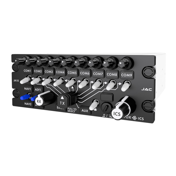
JA10-070 Audio Controller - Ten Transceiver with RX Volume Control Installation and Operating Manual Transceiver receive audio select switches, TX select annunciators and associated legends These are ten white two-position toggle switches positioned round the TX selector control (6). Legend •... -
Page 23: Emer Legend
JA10-070 Audio Controller - Ten Transceiver with RX Volume Control Installation and Operating Manual EMER Legend The EMER (Emergency) legend marks the Emergency position of the Transmit selector (5). To select emergency mode, the control must be pulled and turned to the EMER position. -
Page 24: User 1 Tx Annunciator
Note: Numbers in parentheses refer to the front panel controls shown in section 3.2. The JA10-070 is in Normal mode when the front panel TX selector (6) is in any of the COM 1 through COM 9 or AUX positions (not EMER) and suitable electrical power is supplied to the unit and the optional control panel has the EMER/NORM switch in the NORM position.. -
Page 25: Duplex Operation
The ICS audio level at the phones is controlled by the ICS volume control (9). 3.3.7 ICS Isolate Operation The JA10-070 can be connected to an external ICS ISOLATE switch that will isolate the USER 1 and / or USER 2 from the USER 3 to 8 ICS audio. -
Page 26: User 2 Normal Operation Mode
USER 3 to 8 will hear the music audio as via either the USER 1 or USER 2 music inputs, as configured by ProCS™. Emergency Operation Mode The JA10-070 is in emergency mode when aircraft electrical power is lost or if Emergency Mode has been selected on the JA10-070 Front Panel TX and EMER Select switch, the optional control device EMERGENCY/NORMAL select switch, or the optional external EMERGENCY/NORMAL select switch. -
Page 27: Selected Emergency Mode
If Emergency mode has been selected from the control device or from an external emergency/normal switch, and sufficient power is applied to the JA10-070, the JA10-070 is considered to be in Selected Emergency Mode. In Selected Emergency Mode the sum of the COM 1 receive, NAV 1 receive, DIRECT 1 to 4 and MESSAGE audio is routed to the USER 1 PHONES and the USER 1 CVR. -
Page 28: Appendix A - Installation Drawings
Appendix A - Installation Drawings Introduction The drawings necessary for installation and troubleshooting of the JA10-070 Audio Controller - Ten Transceiver with RX Volume Control are in this Appendix, as listed below. Note: A fully customized set of Connector Maps and Interconnects can be created using the ProCS software. - Page 29 09-30-20 CHECKED TITLE Audio Controller - Ten Transceiver with RX Volume Control P1 - Receive Connector 09-30-20 APPROVED NCAGE CODE PART NO. SHEET L00N3 JA10-070 DOC NO. JA10-070 Connector Map Rev A JUPITER AVIONICS TEMPLATE AUTOCAD PORTRAIT SIZEA REV B.DWT...
- Page 30 09-30-20 CHECKED TITLE Audio Controller - Ten Transceiver with RX Volume Control P2 - Transmit Connector 09-30-20 APPROVED NCAGE CODE PART NO. SHEET L00N3 JA10-070 DOC NO. JA10-070 Connector Map Rev A JUPITER AVIONICS TEMPLATE AUTOCAD PORTRAIT SIZEA REV B.DWT...
- Page 31 09-30-20 CHECKED TITLE Audio Controller - Ten Transceiver with RX Volume Control P3 - Control Connector 09-30-20 APPROVED NCAGE CODE PART NO. SHEET L00N3 JA10-070 DOC NO. JA10-070 Connector Map Rev A JUPITER AVIONICS TEMPLATE AUTOCAD PORTRAIT SIZEA REV B.DWT...
- Page 32 09-30-20 CHECKED TITLE Audio Controller - Ten Transceiver with RX Volume Control P4 -Chassis Ground Connector 09-30-20 APPROVED NCAGE CODE PART NO. SHEET L00N3 JA10-070 DOC NO. JA10-070 Connector Map Rev A JUPITER AVIONICS TEMPLATE AUTOCAD PORTRAIT SIZEA REV B.DWT...
- Page 33 CHECKED TITLE Audio Controller - Ten Transceiver with RX Volume Control P5 - Audio Configuration Connector 09-30-20 APPROVED NCAGE CODE PART NO. SHEET L00N3 JA10-070 DOC NO. JA10-070 Connector Map Rev A JUPITER AVIONICS TEMPLATE AUTOCAD PORTRAIT SIZEA REV B.DWT...
- Page 34 Audio Controller - Ten Transceiver with RX Volume Control Interconnect Notes APPROVED NCAGE CODE PART NO. SHEET 09-18-20 L00N3 JA10-070 DOC NO. CONFIDENTIAL & PROPRIETARY TO JUPITER AVIONICS CORP. JA10-070 Interconnect Rev A.dwg JUPITER AVIONICS TEMPLATE AUTOCAD PORTRAIT SIZEA REV B.DWT...
- Page 35 + 5 VDC LIGHTS PREPARED CHECKED 08-27-20 TITLE Audio Controller - Ten Transceiver with RX Volume Control P/O J1 Interconnect APPROVED NCAGE CODE PART NO. SHEET 09-18-20 L00N3 JA10-070 DOC NO. JA10-070 Interconnect Rev A.dwg JUPITER AVIONICS TEMPLATE AUTOCAD PORTRAIT SIZEA REV B.DWT...
- Page 36 08-27-20 TITLE Audio Controller - Ten Transceiver with RX Volume Control P/O J1 & P/O J2 Interconnect APPROVED NCAGE CODE PART NO. SHEET 09-18-20 L00N3 JA10-070 DOC NO. JA10-070 Interconnect Rev A.dwg JUPITER AVIONICS TEMPLATE AUTOCAD PORTRAIT SIZEA REV B.DWT...
- Page 37 USER 2 NORM MODE SELECT PREPARED CHECKED 08-27-20 TITLE Audio Controller - Ten Transceiver with RX Volume Control P/O J2 Interconnect APPROVED NCAGE CODE PART NO. SHEET 09-18-20 L00N3 JA10-070 DOC NO. JA10-070 Interconnect Rev A.dwg JUPITER AVIONICS TEMPLATE AUTOCAD PORTRAIT SIZEA REV B.DWT...
- Page 38 PREPARED CHECKED 08-27-20 TITLE Audio Controller - Ten Transceiver with RX Volume Control J3 & J5 Interconnect APPROVED NCAGE CODE PART NO. SHEET 09-18-20 L00N3 JA10-070 DOC NO. JA10-070 Interconnect Rev A.dwg JUPITER AVIONICS TEMPLATE AUTOCAD PORTRAIT SIZEA REV B.DWT...
- Page 39 CHECKED 08-27-20 TITLE Audio Controller - Ten Transceiver with RX Volume Control J2 & J4 Interconnect Options APPROVED NCAGE CODE PART NO. SHEET 09-18-20 L00N3 JA10-070 DOC NO. JA10-070 Interconnect Rev A.dwg JUPITER AVIONICS TEMPLATE AUTOCAD PORTRAIT SIZEA REV B.DWT...
- Page 40 USER 2 MUSIC RIGHT LO PREPARED CHECKED 08-27-20 TITLE Audio Controller - Ten Transceiver with RX Volume Control J3 Interconnect Options APPROVED NCAGE CODE PART NO. SHEET 09-18-20 L00N3 JA10-070 DOC NO. JA10-070 Interconnect Rev A.dwg JUPITER AVIONICS TEMPLATE AUTOCAD PORTRAIT SIZEA REV B.DWT...
- Page 41 0.5 DEG Control SHEET NCAGE CODE PART NO. APPROVED 09-18-20 L00N3 JA10-070 CONFIDENTIAL & PROPRIETARY DOC. NO. MATERIAL: TO JUPITER AVIONICS CORP. JA10-070 Mechanical Installation Rev A.SLDDRW FINISH: DRAWING NOT TO SCALE JUPITER AVIONICS TEMPLATE SOLIDWORKS PORTRAIT SIZEA REVB .DRWDOT...
- Page 42 COM 2 NAV 2 DIR 2 Equipment Block Diagram COM 1 NAV 1 DIR 1 09-18-20 APPROVED NCAGE CODE PART NO. SHEET L00N3 JA10-070 DOC NO. JA10-070 Equipment Block Diagram Rev A.dwg JUPITER AVIONICS TEMPLATE AUTOCAD LANDSCAPE SIZEA REV B.DWT...
- Page 43 Pull the legend away from the faceplate as shown in figure 3. Legend Replacement Ensure the correct legend parts are used on the JA10-070. The JA10 requires legends with part numbers starting with JA10-5 and dead front annunciators with part numbers starting with JA10-7.
-
Page 44: Appendix B - Certification Documents
JA10-070 Audio Controller - Ten Transceiver with RX Volume Control Installation and Operating Manual Appendix B - Certification Documents Rev A Page B1... -
Page 45: B1 Airworthiness Approval
The JA10-070 Installation Manual provides detailed installation instructions and wiring diagrams (Section 2, and Appendices A and B). Power is supplied to the JA10-070 through an existing [ ]-Amp circuit breaker that was previously used by the original audio panel. The net electrical load is unchanged. - Page 46 Refer to the JA10-070 Maintenance Manual. 7. Removal and Replacement Information Refer to Section 2 of this manual - the JA10-070 Installation and Operating Manual. If the unit is removed and reinstalled, a functional check of the equipment should be conducted.
Need help?
Do you have a question about the JA10-070 and is the answer not in the manual?
Questions and answers