Table of Contents

Related Manuals for Jupiter Avionics JA94-001


Summary of Contents for Jupiter Avionics JA94-001
- Page 1 JA94-001 Dual Audio Controller Installation and Operating Manual Rev. B Jupiter Avionics Corporation 1959 Kirschner Road Kelowna BC Canada V1Y 4N7 Tel: +1 778 478 2232 Toll-Free: 1 855 478 2232 www.jupiteravionics.com Rev B Page i...
- Page 2 All rights reserved Jupiter Avionics Corporation (JAC) permits a single copy of this manual to be printed or downloaded for the express use of an installing agency. Any such electronic or printed copy of this manual must contain the complete text of this copyright notice.
-
Page 3: Table Of Contents
JA94-001 Dual Audio Controller Installation and Operating Manual Table of Contents SECTION 1 - DESCRIPTION ..............................1 System Overview ..............................1 Features Overview ..............................1 Inputs and Outputs ..............................2 1.3.1 Inputs ................................2 1.3.2 Outputs ................................2 1.3.3 Bi-directional Ports ............................2 Specifications ................................ - Page 4 JA94-001 Dual Audio Controller Installation and Operating Manual Normal Operation Mode ............................19 3.3.1 Panel Lighting ..............................19 3.3.2 Receiving ............................... 19 3.3.3 Transmitting (Transmit Operation) ........................ 20 3.3.4 COM5 PTT Operation ........................... 20 3.3.4 VOX Operation .............................. 20 3.3.5 ICS Operation ..............................
-
Page 5: Section 1 - Description
NAV1 receiver, and the Left User to COM2 transceiver and NAV2 receiver. The JA94-001 is set up on a per-installation basis using a configuration cable and a PC running the product configuration tool to download system configuration settings via the front panel music / configuration connector. To facilitate future customizations and certification, neither software nor complex electronic devices are used in the JA94- 001 design. -
Page 6: Inputs And Outputs
JA94-001 Dual Audio Controller Installation and Operating Manual Inputs and Outputs Refer to the JA94-001 connector maps for the mating connector designators and pin assignments for the input and output signals. 1.3.1 Inputs Name Type CONFIG DATA TO JA94-001 Data signal... -
Page 7: Specifications
JA94-001 Dual Audio Controller Installation and Operating Manual Specifications 1.4.1 Electrical Specifications Power Input Primary nominal voltage 28 Vdc Maximum voltage 32.2 Vdc Minimum voltage 22.0 Vdc Emergency voltage 18.0 Vdc Power Off Voltage ≤ 15.0 Vdc Input current 0.95 A max 1.4.1.1... - Page 8 JA94-001 Dual Audio Controller Installation and Operating Manual Receive Composite Audio load 600 Ω ± 10% Intercom Tie Line type 1 rated load 2000 Ω ± 10% Intercom Tie Line type 2 rated load 2000 Ω ± 10% Intercom Tie Line type 1 maximum load 666 Ω...
-
Page 9: Mechanical Specifications
4 Dzus fasteners Bonding ≤ 2.5 mΩ Installation kit part number INST-JA94 1.4.3 Flammability of Materials The JA94-001 complies with the requirements of RTCA/DO-160G Sec 26.3.3 "Flammability", through equivalent flammability testing of materials and the Small Parts Exemption. Rev B Page 5... -
Page 10: Section 2 - Installation
Introduction This section contains unpacking and inspection procedures, installation information, and post-installation checks. Continued Airworthiness Maintenance of the JA94-001 is on condition only. Scheduled inspection and/or periodic maintenance of this unit is not required. Unpacking and Inspecting Equipment Unpack the equipment carefully. Check for shipping damage and report any problems to the relevant carrier. Confirm that the Authorized Release Certificate or Certificate of Conformance is included. -
Page 11: Mechanical Installation
2.4.3 Mechanical Installation The JA94-001 can be mounted in any attitude and location with adequate space for the front panel and sufficient clearance for the connector and wiring harness. It requires no direct cooling. Note: During bench test set up, it is normal for the JA94-001 chassis to become warm to the touch. -
Page 12: Adjustments And Configuration Using Procs
Product Configuration Software ProCS™. Configuration data is sent to the JA94-001 via the front panel connector (♫/io), using the Configuration Cables and a computer running the ProCS™ software. For configuration requirements, see section 2.5.1. For full information on the configuration process, and for installation of ProCS™ on your computer, refer to the ProCS™... - Page 13 JA94-001 Dual Audio Controller Installation and Operating Manual 2.5.3.1 Front Panel Switches The Front Panel Switches window is used to specify the text for each legend. Note: If the name of a front panel switch is changed using this software, the change will be incorporated in every other section that refers to that switch name, including the connector maps, to give truly customized installation diagrams.
- Page 14 JA94-001 Dual Audio Controller Installation and Operating Manual 2.5.3.3 Receive Levels The receive and direct audio input level of each of the eight RX and the three DIRECT AUDIO inputs can be adjusted from 1 to 10 Vrms. (Default 7.75 Vrms)
- Page 15 JA94-001 Dual Audio Controller Installation and Operating Manual 2.5.3.4 Transmit Levels The level of each of the six Transceiver MIC output signals can be adjusted from 0.01 to 1 Vrms. (Default 250 mVrms) When the Transmit Timeout check box is checked the transmit time-...
- Page 16 Receive Audio. 2.5.3.8 Connector Pin Configuration Several of the connector pins can be configured to meet the requirements of specific installations. Refer to JA94-001 Interconnect sheet 5 of 6. Direct Audio routing can also be selected in this section.
- Page 17 JA94-001 Dual Audio Controller Installation and Operating Manual Routing for DIRECT 1 and 2 can be selected as shown. 2.5.3.9 Audio Muting (During Transmit) When the Mute RX Audio check box is checked the Receive Audio is muted during transmit (Default checked)
- Page 18 JA94-001 Dual Audio Controller Installation and Operating Manual 2.5.3.11 Music Levels LEFT USER, RIGHT USER and Music Input Levels may be individually adjusted. 2.5.3.12 ICS Tie Line The rated input and output levels of the intercom tie line can be selected as Type 1 or Type 2 (Default Type 2).
-
Page 19: Other Configuration Features
2.7.1. 2.5.4 Other Configuration Features In the JA94-001 Product Information Window, the model number, serial number and check sum of the JA94-001 audio panel can be viewed. Installation Kit The kit required to install this unit is not included with the unit. -
Page 20: Section 3 - Operation
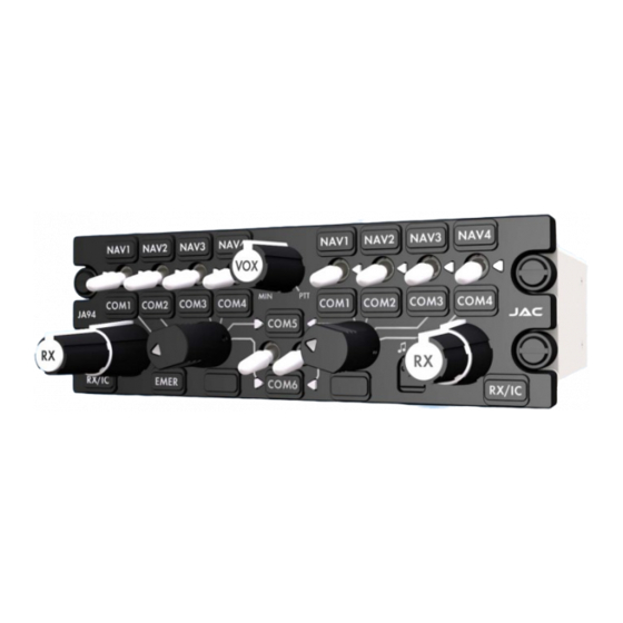
JA94-001 Dual Audio Controller SECTION 3 – OPERATION Introduction This section contains the operating instructions for the JA94-001. Front Panel Controls Note: The 21 legends and 2 deadfront annunciators are removable and may be replaced with custom ordered parts. For the purpose of this manual the controls will be referred to by the default legend and annunciator names as shown below. -
Page 21: Nav1- Com4 Receive Select Switches
JA94-001 Dual Audio Controller Installation and Operating Manual NAV1- COM4 Receive Select Switches and Legends (1) (2) Each User has four white two-position centre-off toggle switches for the NAV1/COM1 to NAV4/COM4 receivers/transceivers. When a left or right switch is set... -
Page 22: Transmit Selector
JA94-001 Dual Audio Controller Installation and Operating Manual Transmit Selector (5) (8) Left User Controls (11) TX Annunciators (12) Right User Controls The Right User TX selector is an unlit rotary seven-position knob that is used to select transmission for one of the six transceivers, or the RMT (remote) position. -
Page 23: Rx/Ics Volume Control And Legend
If in doubt, contact JAC for a list of approved cables, music sources and devices. Normal Operation Mode The JA94-001 is in Normal mode unless EMER mode has been selected via the Left User TX control, or if the power input is off. -
Page 24: Transmitting (Transmit Operation)
JA94-001 Dual Audio Controller Installation and Operating Manual 3.3.3 Transmitting (Transmit Operation) To select a transceiver, rotate the Transmit Select Switch (5) or (8) until it aligns with the line leading to the Transceiver Select switch legend (1) (2) or (3) - default legends COM1, COM2, COM3, COM4, COM5 or COM6. The corresponding Transmit Select annunciator will illuminate green. -
Page 25: Ics Isolation Operation
Remote RMT Operation A remote transmit selector may be linked to the JA94-001 to allow remote selection for transmission via the right user controls. (This remote selector could be on the right user's cyclic control.) When a remote transmit selector is installed and the RIGHT USER TX SELECT switch is in the RMT position, then the RIGHT USER will transmit on the radio or radios as selected by the remote transmit selector. -
Page 26: Emergency Operation Mode
3.4.4 Selected Emergency Mode If the JA94-001 retains power, the unit can be placed into emergency mode by rotating the Left User TX control to the EMER position (pull to turn). Emergency mode conditions will apply (see above) but all other functions of the JA94-001 will operate. The LEDs,... -
Page 27: Appendix A - Installation Drawings
Appendix A - Installation Drawings Introduction The drawings necessary for installation and troubleshooting of the JA94-001 Audio Controller are in this Appendix, as listed below. Note: A fully customized set of Connector Maps and Interconnects can be created using the ProCS™... - Page 28 CHECKED 07-28-15 TITLE Dual Audio Controller P1 Connector Map APPROVED NCAGE CODE PART NO. SHEET 07-28-15 L00N3 JA94-001 DOC NO. CONFIDENTIAL & PROPRIETARY JA94-001 Connector Map Rev A.DWG TO JUPITER AVIONICS CORP. JUPITER AVIONICS TEMPLATE AUTOCAD PORTRAIT SIZEA REV B.DWT...
- Page 29 CHECKED 07-28-15 TITLE Dual Audio Controller P2 Connector Map APPROVED NCAGE CODE PART NO. SHEET 07-28-15 L00N3 JA94-001 DOC NO. CONFIDENTIAL & PROPRIETARY JA94-001 Connector Map Rev A.DWG TO JUPITER AVIONICS CORP. JUPITER AVIONICS TEMPLATE AUTOCAD PORTRAIT SIZEA REV B.DWT...
- Page 30 07-28-15 TITLE Dual Audio Controller P3, P4 Connector Map APPROVED NCAGE CODE PART NO. SHEET 07-28-15 L00N3 JA94-001 DOC NO. CONFIDENTIAL & PROPRIETARY JA94-001 Connector Map Rev A.DWG TO JUPITER AVIONICS CORP. JUPITER AVIONICS TEMPLATE AUTOCAD PORTRAIT SIZEA REV B.DWT...
- Page 31 CONNECTION TO AIRFRAME GROUND SHOULD BE MADE WITH 20 AWG WIRE. LENGTH NOT TO EXCEED 3 FT (0.91 M). CABLE SHIELDS AT THE JA94-001 CONNECTOR PINS SHOULD BE TERMINATED TO AIRFRAME GROUND USING A TAG RING P/N: MS27741-5 OR EQUIVALENT.
- Page 32 + 14 VDC LIGHTS + 5 VDC LIGHTS PREPARED 01-26-16 CHECKED TITLE Dual Audio Controller J1 Interconnect 01-26-16 APPROVED NCAGE CODE PART NO. SHEET L00N3 JA94-001 DOC NO. JA94-001 Interconnect Rev B.dwg JUPITER AVIONICS TEMPLATE AUTOCAD PORTRAIT SIZEA REV B.DWT...
- Page 33 + 28 VDC POWER 20 AWG POWER GROUND AIRFRAME GROUND PREPARED 01-26-16 CHECKED TITLE Dual Audio Controller J2 Interconnect 01-26-16 APPROVED NCAGE CODE PART NO. SHEET L00N3 JA94-001 DOC NO. JA94-001 Interconnect Rev B.dwg JUPITER AVIONICS TEMPLATE AUTOCAD PORTRAIT SIZEA REV B.DWT...
- Page 34 PAX 6 ICS PTT ICS ISOLATION ICS ISOLATE MODE PREPARED 01-26-16 CHECKED TITLE Dual Audio Controller J3 Interconnect 01-26-16 APPROVED NCAGE CODE PART NO. SHEET L00N3 JA94-001 DOC NO. JA94-001 Interconnect Rev B.dwg JUPITER AVIONICS TEMPLATE AUTOCAD PORTRAIT SIZEA REV B.DWT...
- Page 35 HEADSET JACK PAX 4, 5 & 6 PHN LO PREPARED 01-26-16 CHECKED TITLE Dual Audio Controller Interconnect Options 01-26-16 APPROVED NCAGE CODE PART NO. SHEET L00N3 JA94-001 DOC NO. JA94-001 Interconnect Rev B.dwg JUPITER AVIONICS TEMPLATE AUTOCAD PORTRAIT SIZEA REV B.DWT...
- Page 36 COM 6 REMOTE TX SELECT COM 6 DIODES: IN4005 OR EQUIVALENT PREPARED 01-26-16 CHECKED TITLE Dual Audio Controller Interconnect Options 01-26-16 APPROVED NCAGE CODE PART NO. SHEET L00N3 JA94-001 DOC NO. JA94-001 Interconnect Rev B.dwg JUPITER AVIONICS TEMPLATE AUTOCAD PORTRAIT SIZEA REV B.DWT...
- Page 37 ANGLES: 0.5 DEG SHEET NCAGE CODE PART NO. APPROVED 07-28-15 L00N3 JA94-001 CONFIDENTIAL & PROPRIETARY DOC. NO. MATERIAL: TO JUPITER AVIONICS CORP. JA94-001 Mechanical Installation Rev C.SLDDRW FINISH: DRAWING NOT TO SCALE JUPITER AVIONICS TEMPLATE SOLIDWORKS PORTRAIT SIZEA REVB .DRWDOT...
- Page 38 Jupiter Avionics Corporation Audio Controllers Legend Replacement Field-Replaceable Legends Extractor tool Jupiter Avionics Corporation (JAC) products have field-replaceable illuminated recess legends. This permits easy customization, and allows the same units to be used in multiple different configurations with only minimal changes.
-
Page 39: Appendix B - Installation Documents
JA94-001 Dual Audio Controller Installation and Operating Manual Appendix B - Installation Documents Rev B Page B1... -
Page 40: B1 Airworthiness Approval
Removed the existing [model] audio panel and replaced with a Jupiter Avionics JA94-001 Audio Controller in [aircraft location]. Installed in accordance with the JA94-001 Installation Manual, Revision [ ], and AC 43.13-2, Chapters 2, and 3. The JA94-001 interfaces with existing aircraft systems per the Installation Manual instructions. - Page 41 Refer to the JA94-001 Maintenance Manual. 7. Removal and Replacement Information Refer to Section 2 of this manual - the JA94-001 Installation and Operating Manual. If the unit is removed and reinstalled, a functional check of the equipment should be conducted.
Need help?
Do you have a question about the JA94-001 and is the answer not in the manual?
Questions and answers