Table of Contents
Advertisement
Quick Links
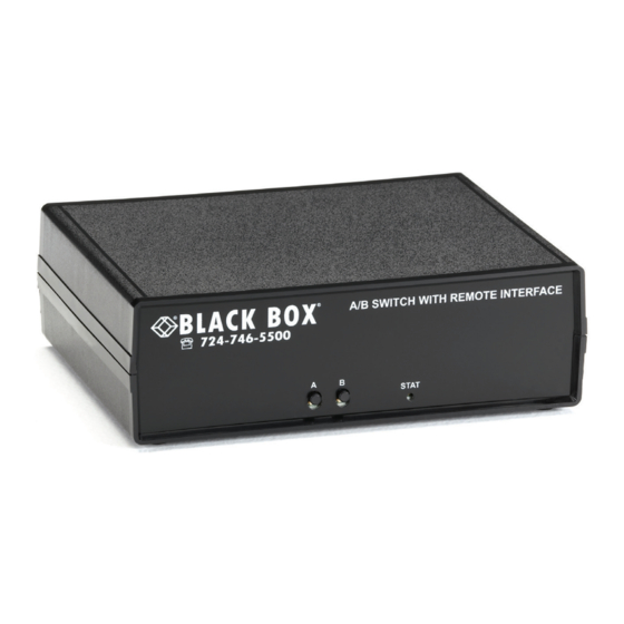
Remotely Controlled Layer 1 A/B Switch, DB9
Switch between two networks or serial segments
with this Layer 1 switch.
SW1046A is a basic DB9 A/B switch with RS-232 Ethernet and
SW1047A is a basic DB9 A/B switch.
Order toll-free in the U.S.: Call 877-877-BBOX (outside U.S. call 724-746-5500)
Customer
FREE technical support 24 hours a day, 7 days a week: Call 724-746-5500 or fax 724-746-0746
Support
Mailing address: Black Box Corporation, 1000 Park Drive, Lawrence, PA 15055-1018
Information
Web site: www.blackbox.com • E-mail: info@blackbox.com
SW1046A
SW1047A
Advertisement
Table of Contents

Related Manuals for Black Box SW1046A


Summary of Contents for Black Box SW1046A
- Page 1 Switch between two networks or serial segments with this Layer 1 switch. SW1046A is a basic DB9 A/B switch with RS-232 Ethernet and SW1047A is a basic DB9 A/B switch. Order toll-free in the U.S.: Call 877-877-BBOX (outside U.S. call 724-746-5500)
- Page 2 Trademarks Used in this Manual Trademarks Used in this Manual Black Box and the Double Diamond logo are registered trademarks of BB Technologies, Inc. Any other trademarks mentioned in this manual are acknowledged to be the property of the trademark owners.
- Page 3 Disclaimer: Black Box Network Services shall not be liable for damages of any kind, including, but not limited to, punitive, consequential or cost of cover damages, resulting from any errors in the product information or specifications set forth in this document and Black Box Network Services may revise this document at any time without notice.
- Page 4 NOM Statement Instrucciones de Seguridad (Normas Oficiales Mexicanas Electrical Safety Statement) 1. Todas las instrucciones de seguridad y operación deberán ser leídas antes de que el aparato eléctrico sea operado. 2. Las instrucciones de seguridad y operación deberán ser guardadas para referencia futura. 3.
-
Page 5: Table Of Contents
5.3 Serial RS-232 Switching ............................... 10 5.4 Ethernet Switching ..............................11 5.5 Automatic Switching ..............................11 6. Ethernet Network Interface Setup (SW1046A) ........................13 7. Console Commands (SW1046A) ............................15 8. Web Interface (SW1046A) ..............................22 9. SNMP MIB Path Summary ..............................24... -
Page 6: Specifications
Additional 20 mA (AC RMS) NOTE: The switching load is constant in the B state, and therefore must be added to the steady state load. Connectors SW1046A: A/B Switch Port: (3) DB9 F, Ethernet Control Port: (1) RJ-45, Serial Control PortL: (1) DB9 F, Remote Control Status Port: (1) 6-position pluggable Phoenix terminal block Power: (1) 3.5-mm power input;... -
Page 7: Introduction
The Remotely Controlled Layer 1 A/B Switch, DB9 (SW1047A and Remotely Controlled Layer 1 A/B Switch, DB9, Ethernet, RS-232 (SW1046A) provide the same basic A/B switch functionality, which is to connect port A or port B to the C (Common) port, through non-latching relays switch mechanisms.The switch will revert to the port C to port A connection state when power is... -
Page 8: Configuration
Jumper Position Function 1–2 position no Ethernet control module (SW1047A) 2–3 position Ethernet control module installed (SW1046A) 1–2 position no Ethernet control module (SW1047A) 2–3 position Ethernet control module installed (SW1046A) NOTE: DIP switch SW1 (resistors may be installed for “closed” positions). -
Page 9: Installation
• If you intend to use serial control (SW1046A), connect a serial cable to the DB9 RS232 console port. The baud rate is fixed at 9600 baud, no parity, 8 data bits, and 1 stop. See Table 6-1 for the console port connector pin assignments. -
Page 10: Operation
Status Relay COMMON Status Relay B contact 5.3 Serial RS-232 Switching (SW1046A) A/B Switch models that support serial remote control can be switched using commands over a serial RS-232 communications line. The parameters of the A/B Switch console port are fixed at 9600 baud, no parity, 8 data bits, and 1 stop bit (commonly abbreviated as 9600, 8, N, 1). -
Page 11: Ethernet Switching
5.4 Ethernet Switching (SW1046A) A/B Switch models (SW1046A) that support Ethernet remote control can be switched using commands sent over an Ethernet net- work. In order to use the Ethernet Network port on the A/B Switch you must set the IPADDRESS, SUBNETMASK, and GATEWAY address parameters before connecting to your network. - Page 12 Chapter 5: Operation Figure 5-1. Auto Failover and Manual Recovery. NOTE: The A/B Switch monitors the WAN connections by PINGing the far side router through the primary WAN link. If the primary WAN link fails, the A/B Switch auto switches to the backup WAN link. Auto recovery is disabled in this configuration to prevent flapping.
-
Page 13: Ethernet Network Interface Setup (Sw1046A)
Chapter 6: Ethernet Network Interface Setup 6. Ethernet Network Interface Setup (SW1046A) To perform initial setup of the network management interface on the A/B Switch you will need a serial terminal capable of 9600 baud, no parity, 8 data bits, and 1 stop bit. Connect this terminal to the DB9 console connector on the A/B Switch. A straight thru M/F cable is required to connect to an IBM PC standard DB9 serial port. - Page 14 Chapter 6: Ethernet Network Interface Setup After the system reinitializes, you will again be greeted by the sign-on message as before. At this time you can connect an Ethernet cable to the 10Base-T network port on the A/B Switch and to an available port on your Ethernet switch or router. The A/B Switch will respond to SNMP, telnet and HTTP messages at the assigned IP address.
-
Page 15: Console Commands (Sw1046A)
Chapter 7: Console Commands 7. Console Commands (SW1046A) The following commands are available from the RS-232 console port or from the Ethernet network port on models of the A/B Switch that support these remote control interfaces. All commands are case insensitive, although several parameters are case sensitive (read/write community names and web and telnet passwords). - Page 16 Chapter 7: Console Commands SET SYSTEM A[B] Sets the system to position A or B. SET IPADDRESS X.X.X.X GET IPADDRESS Set or display the current IP address of the network module. Any change will not become permanent until a SAVE and RESET operation sequence is performed.
- Page 17 Chapter 7: Console Commands SET WEBPASSWORD string GET WEBPASSWORD Set or display the current web password. Note that this is a case sensitive field. Any change will not become permanent until a SAVE and RESET operation sequence is performed. SET WEBTIMEOUT seconds GET WEBTIMEOUT Set or display the current web timeout in seconds.
- Page 18 Chapter 7: Console Commands SET MONITORIP [X.X.X.X] GET MONITORIP Set or display the IP address of the device that the A/B Switch is to PING to determine the active port alternate (A) or normal (B). Setting this to 0.0.0.0 disables the auto switch/recovery function. Any change will not become permanent until a SAVE operation is performed.
- Page 19 Chapter 7: Console Commands SET AUTHENTICATIONTRAP ON[OFF] GET AUTHENTICATIONTRAP Set or display the current state of authentication error traps. Authentication traps will be generated when this parameter is set to ON, and not when OFF. Note that this setting only affects the trap generation, and not how the network module handles an authentication failure.
- Page 20 Chapter 7: Console Commands GET MANAGER N Display SNMP manager N (1-16) IP address. GET MANAGER Display all SNMP manager IP addresses. PING X.X.X.X Causes the A/B Switch to issue a single ICMP echo request packet to the designated IP address. If a response is received, the A/B Switch will display the message “Reply from X.X.X.X”.
- Page 21 Chapter 7: Console Commands HELP Displays a list of commands. >help D1000 CONSOLE COMMANDS: GET ALL (display all parameters) GET VERSION (display software versions) GET[SET] SYSTEM [A/B] (control all system ports) GET[SET] IPADDRESS [X.X.X.X] GET[SET] SUBNETMASK [X.X.X.X] GET[SET] GATEWAY [X.X.X.X] GET[SET] PINGREPLY [ON/OFF] GET[SET] SNMPENABLE [ON/OFF] GET[SET] READCOMMUNITYNAME [string]...
-
Page 22: Web Interface (Sw1046A)
Chapter 8: Web Interface 8. Web Interface (SW1046A) The network module installed in Ethernet remote control capable models of the A/B Switch also provides access to console commands through a web browser interface. When enabled (see SET WEBENABLE command) entering the A/B Switch’s IP address (index.html) in your web browser’s URL address line will present a log on page for the A/B Switch similar to the following... - Page 23 Chapter 8: Web Interface At this point you may enter any valid command into the text box and click “Send Command” to execute. The following is an example result of the GET ALL command. Figure 8-3. Example Command Results screen. The A/B Switch will only allow 1 telnet or web access session.
-
Page 24: Snmp Mib Path Summary
Chapter 9: SNMP MIB Path Summary 9. SNMP MIB Path Summary [internet] – 1.3.6.1 [private] – 1.3.6.1.4 [enterprises] – 1.3.6.1.4.1 [mctech] – 1.3.6.1.4.1.9477 [mctech] – 1.3.6.1.4.1.9477 Market Central, Inc. private enterprise number [mcAgent] – 1.3.6.1.4.1.9477.1 Market Central, Inc. SNMP Agent The following is a list of the SNMP variables corresponding to: D1000 A/B Switch. -
Page 25: Traps Summary
Chapter 10: Traps Summary 10. Traps Summary The A/B Switch can be configured to issue an SNMP trap when certain events occur. Use the “SET ALERTTYPE” command to enable traps, and use the “SET MANAGER N X.X.X.X” command to specify the IP addresses of up to 16 different NMS computers that you want to send these traps to (see Section 7 for details regarding these commands). -
Page 26: Syslog Messages
Chapter 11: Syslog Messages 11. Syslog Messages The A/B Switch can be configured to issue a syslog message rather than an SNMP trap when certain events occur. To configure the A/B Switch to issue syslog messages, you must use the “SET ALERTTYPE” command to select SYSLOG messages, and you need to specify the IP address(es) of the device(s) that will be receiving the syslog messages by using the “SET MANAGER N X.X.X.X”... - Page 27 NOTES 724-746-5500 | blackbox.com Page 27...
- Page 28 About Black Box Black Box provides an extensive range of networking and infrastructure products. You’ll find everything from cabinets and racks and power and surge protection products to media converters and Ethernet switches all supported by free, live 24/7 Tech support available in 60 seconds or less.
Need help?
Do you have a question about the SW1046A and is the answer not in the manual?
Questions and answers