
Related Manuals for FMS Super Scorpion 90MM


Summary of Contents for FMS Super Scorpion 90MM
- Page 1 90MM Super Scorpion FMSMODEL.COM DETAILED RIGID STABLE RETRACT & FLAPS INSTALLED STRONG DURABLE EPO SMOOTH FLYING PERFORMANCE...
- Page 3 WARNING: Read the ENTIRE instruction manual to become familiar with the features of the product before operating. Failure to operate the product correctly can result in damage to the product, personal property and cause serious injury. This is a sophisticated hobby product and NOT a toy. It must be operated with caution and common sense and failure to do so could result in injury or damage to the product or other property.
-
Page 4: Table Of Contents
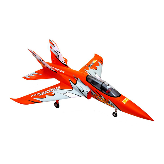
EDF and the 3546-KV1900 motor system provides tremendous power and speed when coupled with a 6S battery. The vibrant orange color scheme makes this airplane look fantastic on the ground and in the air... No matter whether you’ve had a Super Scorpion before or not, the coming FMS 90mm Super Scorpion is full of surprises. -
Page 5: Contents Of Kit
Wingspan: 1140mm (44.9in) Overall Length: 1320mm (52in) Flying Weight: Around 3200g (112.9oz) Motor Size: Brushless 3546-KV1900 Wing Load: 108.8 g/dm² (0.25oz/in²) Wing Area: 29.4 dm² (455.7 sq.in) ESC: 130A with 10A UBEC Servo: 17g Servo x 4, 13g Servo x 5 Contents of Kit Before assembly, please inspect the contents of the kit. -
Page 6: Model Assembly
Model Assembly Main Wing Installation 1. Slide the tube into the fuselage then install both wings over the wing tube and into the wing slot of the fuselage. (fig1) fig1... - Page 7 Model Assembly 2.Secure the both wings into the fuselage using the included 4 screws. (fig2) Note: The connectors on both sides should be attached precisely and firmly. HKM3.0*16 fig2...
- Page 8 Model Assembly Horizontal Stabilizer Installation: 1.Connect the elevator servo connectors to the servo extensions in the fuselage. 2.Insert the horizontal tail in the rear of the fuselage. Ensure the control horn faces down as shown. (fig3) 3.Secure the horizontal tail in place using the included screws. (fig4) fig3 HKM3.0*10 fig4...
- Page 9 Model Assembly Vertical Stabilizer Installation: 1.Connect the rudder servo connectors to the servo extensions in the fuselage and then put it in the slot. 2.Insert the vertical tail into the slots in the fuselage. (fig5) 3.Secure the vertical tail in place using the included screws. (fig6) fig5 HKM3.0*26 HKM3.0*32...
-
Page 10: Battery And Radio Installation
Battery and radio installation 1. Pull back on the release button and remove the battery hatch. 2. Apply the loop side (soft side) of the hook and loop tape to the bottom of the battery and the hook side to the battery tray. 3.Install the fully charged battery in the battery compartment with the power supply cable toward the nose end of the plane, and secure using the hook and loop straps. -
Page 11: Important Esc And Model Information
Get your model ready to fly Important ESC and model information The ESC included with the model has a safe start. If the motor battery is connected to the ESC and the throt- tle stick is not in the low throttle or off position, the motor will not start until the throttle stick is moved to the low throttle or off position. -
Page 12: Check The Control Throws
Check the control throws The suggested control throw setting for FMS MODEL are as follows (dual rate setting): Tips: On first flight, fly the model in low rate. The first time you use high rates, be sure to fly at low to medium... -
Page 13: Clevis Installation
Clevis Installation a. Pull the tube from the clevis to the linkage. b. Carefully spread the clevis, then insert the clevis pin into the desired hole in the control horn. c. Move the tube to hold the clevis on the control horn. Control Horn and Servo Arm Settings The table shows the factory settings for the control horns and servo arms. -
Page 14: Center Of Gravity
Check the C.G. (Center of Gravity) When balancing your model, adjust the motor battery as necessary so the model is level or slightly nose down. This is the correct balance point for your model. After the first flights, the CG position can be adjusted for your personal preference. -
Page 15: Before Flying The Model
Before flying the model Find a suitable flying site Find a flying site clear of buildings, trees, power lines and other obstructions. Until you know how much area will be required and have mastered flying your plane in confined spaces, choose a site which is at least the size of two to three football fields - a flying field specifically for R/C planes is best. -
Page 16: Flying Your Model
Flying your model Take off While applying power, slowly steer to keep the model straight. The model should accelerate quickly. As the model gains flight speed you will want to climb at a steady and even rate. It will climb out at a nice angle of attack (AOA). -
Page 17: Troubleshooting
Troubleshooting Possible Cause Solution Problem Aircraft will not - Lower throttle stick and throttle - ESC is not armed. respond to the trim to lowest settings. - Throttle channel is reversed. throttle but responds - Reverse throttle channel on to other controls. transmitter. -
Page 18: Spare Parts List Content
Spare parts list content FMSRA101 Fuselage FMSRA102 Main Wing Set FMSRA103 Vertical Stabilizer FMSRA104 Horizontal Stabilizer FMSRA105 Canopy FMSRA106 Cowl FMSRA107 Nozzel FMSRA108 Linkage Rod FMSRA109 Stickers FMSRA110 Screw Set FMSRA111 Control Horns FMSRA112 Wheel Set FMSRA113 Pipe FMSRA114 Front Landing Gear Set FMSRA115 Main Landing Gear Set FMSRA116... -
Page 19: Esc Instruction
ESC instruction Wires Connection: The electronic speed controller can be connected to the motor by soldering directly, or with high quality connectors. Always use new connectors, which should be soldered carefully to the cables and insulated with heat shrink tubes. The maximum length of the battery pack wires should be within 6 inches. - Page 20 Our ESC allows you to program parameters to fit your specific needs: 1. User programmable brake setting (we recommend using brake for only folding props applications) 2. User programmable battery type (LiPo or NiCd/NiMh) 3. User programmable low voltage cutoff setting 4.
- Page 21 5. Timing setup: Automatic / Low / High. * Automatic – ESC automatically determines the optimum motor timing * Low (7-22 deg) – Setting for most 2 pole motors. * High (22-30 deg)-setting for motors with 6 or more poles. In most cases, automatic timing works well for all types of motors.
- Page 22 Using Your New ESC Improper polarity or short circuit will damage the ESC therefore it is your responsibility to double check all plugs for proper polarity and firm fit BEFORE connecting the battery pack. Alert Tones The ESC is equipped with audible alert tones to indicate abnormal conditions at power up. If the ESC can't enter into working mode after powering up, it indicates that you have not setup throttle calibration.
- Page 23 Built-in Intelligent ESC Safety Functions 1. Over-heat protection: When the temperature of ESC exceeds 110 deg C, the ESC will reduce the output power to allow it too cool. 2. Lost Throttle signal protection: The ESC will automatically reduces output power to the motor when it detects a lost of throttle signal for 2 second, a subsequent loss of throttle signal beyond 2 seconds, will cause the ESC automatically to cut power to the motor.
- Page 24 ●Never use ruptured or punctured battery cells. ●Never use battery packs that are known to overheat. ●Never short circuit battery or motor terminals. ●Always use proper insulation material for cable insulation. ●Always use proper cable connectors. ●Do not exceed the number of cells or servos specified by the ESC. Wrong battery polarity will damage the ESC and void the warranty.
- Page 25 Motor doesn’t work after powering up Check and verify that the ESC cable The ESC is unable to detect the the ESC. An alert tone with a single is connected to the Throttle channel normal throttle signal from the receiver beeping tone followed by a short on the receiver.
Need help?
Do you have a question about the Super Scorpion 90MM and is the answer not in the manual?
Questions and answers