Table of Contents
Advertisement
Advertisement
Table of Contents

Related Manuals for Apevia X-Sniper

Summary of Contents for Apevia X-Sniper
- Page 1 USER’S MANUAL...
-
Page 2: Table Of Contents
1. Motherboard installation...1 2. Install 3½” and 5¼” 3. Install PCI components...4 4. Case fan setup...5 5. Front fan installation (optional)...6 6. Temperature probe setup...7 Connect case leads to motherboard 8. Case accessories...8 Identify the power supply connectors 10. Complete the installation...10 11. -
Page 3: Motherboard Installation
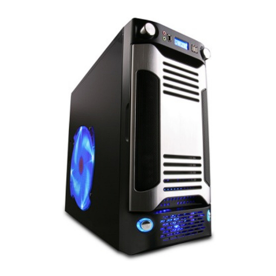
NOTE: CPU and memory installation is not covered in this manual. Please refer to each components’ documentation for instructions. 1. Motherboard installation: 1.1 Remove thumbscrews from the rear of the X-Sniper. X-Sniper Mid Tower Chassis 1.2 Grab the notch on the left panel. Pull until panel is released and remove. - Page 4 1.3 Likewise for the S Type, grab the notch on the left panel and pull until the panel is released. NOTE: Touch an unpainted metal section of the chassis to discharge static electricity before handling PC components. An anti-static wrist strap should also be worn to further minimize the possibility of damage.
-
Page 5: Install 3½" And 5¼" Drives
2. Install 3½” and 5¼” 2.1 To install an optical or floppy drive, remove the drive cover by placing a flathead screwdriver into either inlet and prying outward. Finish by using hand to remove slot cover. 2.3 Insert optical drive into drive bay until the drive is flush with the slot covers. -
Page 6: Install Pci Components
2.5 For hard-drives, locate the blue drive rails labeled “HDD” and attach one to each side of the drive. 3. Install PCI components: 3.1 First, remove the PCI slot covers. Firmly press point A with thumb, while pulling point B with index finger to open the latch. -
Page 7: Case Fan Setup
3.3 1st, read your expansion card’s documentation. Install PCI card into correct slot for your card type (x1, x16, etc.). 4. Case fan setup: 4.1 Daisy chain the side case fan to the optional front fan, (installation covered in step 5) as they both function as intake fans. -
Page 8: Front Fan Installation (Optional)
5. Front fan installation (optional): 5.1 To install a 120mm fan for improved cooling, first remove the hard-disk cage by removing the screws shown. There are also two screws on the un- derside of the case that will need to be removed. -
Page 9: Temperature Probe Setup
6. Temperature probe setup: 6.1 Locate the device temperature probes. Tape the probe labeled ‘CPU’ to any ‘fin’ on the CPU’s heatsink and tape in place. For best results, use thermal tape. Note: You may also leave a sensor loose in the chassis in order to monitor the ambient system temperature. -
Page 10: Connect Case Leads To Motherboard
7. Connect case leads to motherboard: 7.1 Locate the front panel leads. Your motherboard documentation will provide schematics. The triang- ular markings indicate the positive pins/wires. (Remove right-side panel to better access wiring.) Case accessories: The RF choke is used to suppress radio frequency interference. -
Page 11: Identify The Power Supply Connectors
9. Identify the power supply connectors: (For power supply version only) 9.1 20/24 pin ATX main connector 9.3 Serial ATA (SATA) connector 9.5 6-pin PCI-Express connector Connect PC components to the required power connector for each device type. 9.2 ATX 12V CPU connector 9.4 4-pin peripheral connector 9.6 Floppy drive connector... -
Page 13: Complete The Installation
10. Complete the installation: 10.1 With all components properly installed, gently return side panels to their original positions and replace all screws. Congratulations! You have completed assembly of the X-Sniper. 11. USB/1394/Audio cable pin assignments:...
Need help?
Do you have a question about the X-Sniper and is the answer not in the manual?
Questions and answers