Table of Contents
Advertisement
Quick Links
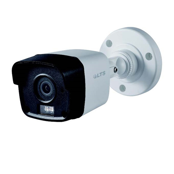
HD-TVI
Bullet Camera
User Manual
User Manual
Thank you for purchasing our product. If there are any
questions, or requests, please do not hesitate to
contact the dealer.
This manual may contain several technical incorrect
places or printing errors, and the content is subject to
change without notice. The updates will be added to
the new version of this manual. We will readily improve
or update the products or procedures described in the
manual.
Available from A1 Security Cameras
Advertisement
Table of Contents

Related Manuals for LTS CMHR64T2W-28


Summary of Contents for LTS CMHR64T2W-28
- Page 1 HD-TVI Bullet Camera User Manual User Manual Thank you for purchasing our product. If there are any questions, or requests, please do not hesitate to contact the dealer. This manual may contain several technical incorrect places or printing errors, and the content is subject to change without notice.
-
Page 2: Regulatory Information
Privacy Notice Surveillance laws vary by jurisdiction. Check all relevant laws in your jurisdiction before using all this product for surveillance purpose to ensure that your use of this product conforms. Regulatory Information FCC Information FCC compliance: This equipment has been tested and found to comply with the limits for a digital device, pursuant to part 15 of the FCC Rules. -
Page 3: Product Features
1 Introduction 1.1 Product Features This series of camera adopts high performance sensor and advanced circuit board design technology. It features high resolution, low distortion, and low noise, etc. It is suitable for surveillance system and image process system. The main features are as follows: ... -
Page 4: Installation
2 Installation Before you start: Please make sure that the device in the package is in good condition and all the assembly parts are included. Make sure that all the related equipment is power-off during the installation. Check the specification of the products for the installation environment. - Page 5 3). Loosen the R screw and rotate the camera [0°~360°] to adjust the lens to the surveillance angle. Tighten the screw after completing the adjustment. Pan Position Range [0°-360°] P Screw Tilt Position Range [0°-180°] T Screw Rotation Position Range R Screw [0°-360°] Figure 2-2 3-axis Adjustment...
- Page 6 Figure 2-5 Fix the Camera to the Ceiling/Wall 6. Refer to step 5 of 2.1.1 to adjust the camera to get an optimum angle. 2.2 Installation of Type II Camera 2.2.1 Ceiling/Wall Mounting without Gang Box Steps: Attach the drill template (supplied) to the place where you want to fix the camera, and then drill the screw holes and the cable hole in the ceiling/wall according to the drill template.
- Page 7 2.2.2 Ceiling/Wall Mounting with Gang Box You need to purchase a gang box separately if you adopt celling mounting. Steps: Take apart the gang box and align the screw holes of the bullet camera and the gang box cover. Figure 2-8 Gang Box Route the cables through the cable hole of gang box and fix the camera with the gang box cover with the supplied screws, as shown in Figure 2-9.
-
Page 8: Menu Description
3 Menu Description SETUP FORMAT MAIN MENU VIDEO RESET &NIGHT SETTING SAVE CONTRAST &EXIT BRIGHTNESS COLOR SHARPNESS EXPOSURE MODE COLOR GAIN GAIN SMART MIRROR Figure 3-1 Main Menu Overview With a camera controller (purchased separately) or calling the preset No. 95 of DVR you can select the menu and adjust the parameters. - Page 9 distribution, variations, non-standard processing, or other conditions of under exposure to get an optimum image. BLC (Backlight Compensation) BLC (Backlight Compensation) compensate light to the object in the front to make it clear, but this causes the over-exposure of the background where the light is strong.
- Page 10 INFRARED You can select to turn on/off the IR LED to response to the requirements of different circumstances. SMART IR The Smart IR function is used to adjust the light to its most suitable intensity, and to prevent the image from over exposure.
Need help?
Do you have a question about the CMHR64T2W-28 and is the answer not in the manual?
Questions and answers