Table of Contents
Advertisement
Quick Links
Advertisement
Table of Contents

Related Manuals for Acnodes PM 610


Summary of Contents for Acnodes PM 610
-
Page 1: User Manual
User Manual PM 610... -
Page 2: Table Of Content
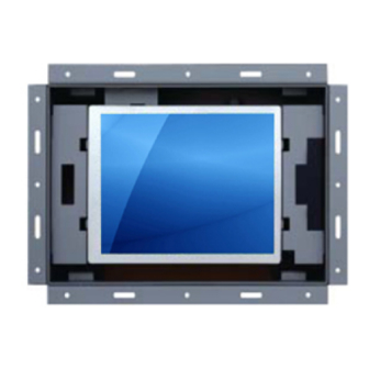
Table of Content Introduction Installation Using the System Jan 05 1. Table of Content A) Overview B) Features C) Dimension Diagrams D) Technical Specifications A) Package Contents B) Caution to the user C) Cleaning D) Precautions A) Product Views B) I/O Outlet C) Installation Procedures D) Setup Touchscreen (Optional) For Windows... - Page 3 Overview This LCD monitor incorporates 6.4 color active matrix thin-film-transistor (TFT) liquid crystal display to provide superior display performance. A maximum resolution of 640 x 480 is ideal for displaying complex graphics and high defi- nition images. Other outstanding designs that enhance this LCD monitor s performance are Plug &...
- Page 4 User Manual 2. Introduction Dimension Diagrams PM 610 Jan 05...
- Page 5 Monitor Power Supply Connectors Video Product Dimension Packing Jan 05 2. Introduction Technical Specifications Panel 6.4" LCD Panel Display Type TFT LCD active matrix colour Resolutions 640 x 480 Response Time Tr=30ms, Tf=50ms Contrast Ratio 180:1 typical Brightness 300 cd/m Pixel Pitch 0.203(H) x 0.203(V) Panel Colour...
- Page 6 Package Contents After unpacking the carton, check and see if the following items are included in good condition. Contact your supplier as soon as possible for replacing the missing / damaged items. 6.4 TFT LCD monitor VGA Cable (Male to Male) DC 12V Adapter Power Cord Mounting Bracket (AP Series only)
- Page 7 Precautions Read all of these instructions and save them for later use. Follow all warnings and instructions on the product. Product Do not cover or block the vent holes in the case. Do not insert sharp objects or spill liquid into the LCD monitor through cabinet slots.
- Page 8 Precautions (Cont.) Power and extension cords 1. Do not allow anything to rest on the power cord. 2. Do not locate this product where persons will walk on the cord. 3. Use the proper power cord with correct attachment plug type. If the power source is 120V AC, use a power cord that has UL and C-UL approvals.
- Page 9 User Manual 4. Using the System Product Views (Cont.) PM 610 - Front View PM 610 - Rear View Jan 05 P.12...
- Page 10 I/O Outlet (1) DC IN (2) PC IN (3) S-Video IN (4) RCA IN Jan 05 4. Using the System Front This is for connecting the power cable. This can be connected with the D-Sub 15 pin signal connector. This can be connected with the S-Video cable connector. (for AV series only) This can be connected with the composite cable connector.
- Page 11 Installation Procedures This monitor is equipped with an auto-sensing power supply for voltage ranges 100~240V, 50~60Hz. Please follow the following instruction to install LCD monitor. 1. Make sure that the system power is turned off. 2. Plug the signal cable to the signal connector at the rear of PC and the rear of the LCD monitor.
- Page 12 Setup Touchscreen Touchscreen used for UltraView products are manufactured by 3M. Here provide TouchWare Note: To configure the settings of the touchscreen, please refer to the TouchWare Note: If you have a Microsoft® IntelliPoint® or Kensington® Mousework® PS/2 mouse, installing TouchWare functionally of these devices For Windows 95, 98, Me, NT4.0, 2000 &...
- Page 13 Setup Touchscreen For Windows 95, 98, Me, NT4.0, 2000 & XP (Cont.) Once installation is complete, restart the system. As the system restarts, Windows detects and loads the driver. For serial controllers, restart the system. As the system restarts, Win- dows detects and load the driver Note: For USB controllers, connect the touch screen cable to the USB port in...
- Page 14 Setup Touchscreen For DOS (Cont.) Type INSTALL followed by the source disk drive, the destination drive, and the destination directory. For example, the following command copies the files from Drive A (source drive) to Drive C (destination drive) and the \MTS\TOUCH directory : INSTALL A: C:\MTS\TOUCH Press Enter.
- Page 15 Setup Touchscreen For DOS (Cont.) After you install the files for the DOS touchscreen driver, you must load the driver before you can run a DOS touch application or open the DOS Touchscreen control panel. You can run the DOS touchscreen driver from a full-screen DOS session within Windows.
- Page 16 OSD Switch Jan 05 4. Using the System Input Select: This button is used to select CVBS for composite video input, RGB for VGA input and S-Video for Super-Video input OSD Menu: This button is used to enter OSD main Menu Increase(à): This button is used to adjust the increasing or next value of selected OSD control option.
-
Page 17: Main Menu
LCD Membrane Diagram Main Menu Bright / Contrast To enter into the Bright, Black level & Contrast sub-menu Auto Adjust To perform automatic optimisations of all functions An Adjusting message is displayed during the process Phase / Clock To enter into the phase & clock sub menu H/V Position To enter into the Position sub-menu MISC... - Page 18 OSD Control For VGA Input Version Bright / Contrast 1. Brightness To perform brightness adjustment of the input RGB signal Use the Left & Right button to adjust and button 2. Contrast To adjust the contrast level of the input signal Use the Left &...
- Page 19 OSD Control For VGA Input Version MISC 1. Information The first header row shows the current resolution setup The second header row shows the horizontal frequency of the current input signal The third header row shows the vertical frequency of the current input signal 2.
-
Page 20: Colour Configuration Page
OSD Control For Video Input Version Jan 05 4. Using the System Colour Configuration Page Colour Brightness Contrast Colour Adjust Exit Brightness Adjust the brightness value from 1 to 100 using (à) and (ß) buttons. Contrast Adjust the contrast value from 1 to 100 using (à) and (ß) buttons. - Page 21 OSD Control For Video Input Version Jan 05 4. Using the System Picture Configuration Page Picture H.Position V.Position Sharpness Phase Clock Exit H.Position Press (à) shifting display image to right with value from 0 to 100; Press (ß) shif ting display im age to lef t f rom v alue 0 to 100. V.Position Press (à) shifting display image to upward with value from 0 to 100;...
-
Page 22: Auto Adjust
OSD Control For Video Input Version Jan 05 4. Using the System Function Configuration Page Function Auto Adjust Auto Position Auto Phase Auto Clock Exit Auto Adjust Enable or disable function for auto adjusting brightness, contrast, color etc. Enable Auto Position Enable or disable function for auto adjusting horizontal position or vertical position Enable... -
Page 23: Osd Timer
OSD Control For Video Input Version Jan 05 4. Using the System OSD Menu Configuration Page OSD Menu Language OSD H.Position OSD V.Position OSD Timer Translucent Exit Language Change language of OSD Menu for English or traditional Chinese OSD H.Position Press (") shifting OSD Menu to right with value from 0 to 100;... -
Page 24: Miscellaneous Configuration Page
OSD Control For Video Input Version Jan 05 4. Using the System Miscellaneous Configuration Page Miscellaneous Mode Select Reset Exit Mode Select Switch the display size for 640 x 400 or 720 x 400 in DOS mode Reset Enter for reloading all factory default Exit Exit the Function configuration Page P.27...
Need help?
Do you have a question about the PM 610 and is the answer not in the manual?
Questions and answers