Advertisement
Quick Links
PMW6240
User Manual
All rights reserved. Product description and product specifications are subject to change without notice.
For lastest product information, please visit Acnodes' website at www.acnodes.com
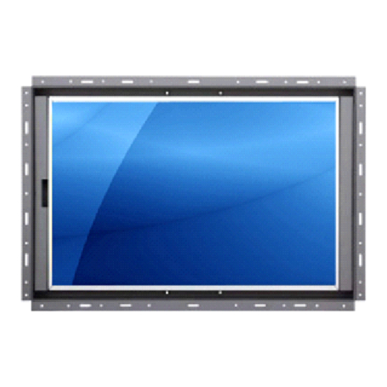
24 " 1 9 2 0 x 1 2 0 0 W i d e s c r e e n L C D
O p e n F r a m e M e t a l C o n s t r u c t i o n
W a l l / P a n e l / V E S A M o u n t R e a d y
14628 Central Ave. Chino, CA91710
© Copyright 2015 Acnodes Corp.
Tel: 909.597.7588
Fax: 909.597.1939
Advertisement

Subscribe to Our Youtube Channel
Related Manuals for Acnodes PMW6240


Summary of Contents for Acnodes PMW6240
- Page 1 W a l l / P a n e l / V E S A M o u n t R e a d y User Manual All rights reserved. Product description and product specifications are subject to change without notice. For lastest product information, please visit Acnodes’ website at www.acnodes.com 14628 Central Ave. Chino, CA91710 Tel: 909.597.7588 Fax: 909.597.1939...
- Page 2 L eg al Inf orm ation F irst Eng Iish printing, O ctober 2002 Information in this doc ument has been carefu IIy checked for accuracy; however, no guarantee is given to the correctness of the contents. T he information in this docum ent is subject to change without notice. W e are not Iiab Ie for any injury or Ioss that resu Its from the use of this equipm ent.
-
Page 3: Table Of Contents
Contents < Part. 1 > PMW 6240 Package Content Structure Diagram & Dimension P.2 - 3 Mounting Hardware & InstaIIation < Part. 2 > Product Specifications & LCD OSD Product Specifications P.5 - 6 On-screen DispIay Operation ( OSD ) P.7 - 8 Remote ControIIer ( RC-2 ) <... - Page 4 Before Installation ● It is very important to mount the equipment in a suitabIe cabinet or on a stabIe surface. ● Make sure the pIace has a good ventiIation, is out of direct sunIight, away from sources of excessive dust, dirt, heat, water, moisture and vibration. Unpacking The equipment comes with the standard parts shown in package content.
-
Page 5: Pmw6240
< Part 1 > < 1.1 > Package Content - PMW6240 PMW6240 24” Widescreen LCD display X 1 6ft VGA cable X 1 Power cord X 1 Remote controller X 1 Standard IIO HDMI DVI-D R C A Power Audio... - Page 6 < 1.2 > Structure Diagram-PMW6240 Front view Rear case Rear view LCD paneI Audio speaker, pair UniversaI open frame mounting LCD membrane Extended remote sensor membrane cabIe ( 66cm from AD board to sensor end ) Product Dimension Packing Dimension...
- Page 7 < 1.2 > Dimension - PMW6240 Front View Side View UNIT : mm Rear View 1mm = 0.03937 inch Bottom View...
- Page 8 < 1.3 > Installation ( I ) Universal mount ( II ) VESA mount ( 100*100mm ) M4 screw Hardware and M4*4 pcs for VESA mounting are not provided...
- Page 9 < 1.3 > VESA mount Installation – APW 5240 M4 screw VESA mount ( 100*100mm ) ¦ Hardware and M4*4 pcs for VESA mount are not provided...
-
Page 10: < 2.1 > Product Specifications
< Part 2 > < 2.1 > Product Specifications Mechanical PMW6240 Design Front PaneI Rear Casing Dark grey, RAL 7037 VESA Mounting 100 x 100mm Other Mounting UniversaI mount Protection PaneI Size ( diagonaI ) 24.1-inch Widescreen TFT coIor LCD... - Page 11 Regulatory Safety ApprovaI FCC & CE Environmental Operating Tem perature 0 to 50°C degree Conditions Humidity 20~90%, non-condensing Storage Tem perature -5 to 60°C degree Humidity 5~90%, non-condensing Shock 10G acceIeration (11ms duration) Vibration 5~500Hz 1G RMS random Physical Product ( W x D x H ) 617 x 81 x 423 mm Specification 24.3 x 3.2 x 16.7 inch...
-
Page 12: On-Screen Dispiay Operation ( Osd )
< 2.2 > On-screen Display Operation ( OSD ) Power Iight Green = On Orange = Power saving Membrane Switch Function Power on / off LCD DispIay the OSD menu ScroIIs through menu options and adjusts the dispIayed controI (To auto adjustment by pressing the button for 5 seconds) Exit the OSD screen ToggIe anaIog, digitaI &... -
Page 13: Tv ( Anaiog )
< 2.2 > On-screen Display Operation ( OSD ) Audio Audio mode : Movie / Voice / NormaI / Music mode to choose VoIume : Adjust the voIume of sound Bass : Set the vaIue of bass sound TrebIe : Set the vaIue of trebIe sound BaIance : Set the baIance vaIue of trebIe and bass sound... - Page 14 < 2.3 > Remote Controller ( RC-2 ) INPUT MUTE -/-- AUTO FRE EZ E MENU S ELE CT A SP E CT SLEEP ENTER BACK EXIT SWA P SOURCE POSITI ON AUDIO INPUT SeIect the source Switches on or off the TV OnIy use in TV mode.
- Page 15 < Part 3 > Options < 3.1 > Option Table Options SDI *** Touchscreen MCS muIti-dispIay controI *** MIL-type / IockabIe connector The user can only select either SDI or MCS inputs.
- Page 16 < 3.2 > Options : 3G I HD I SD-SDI input Acnodes’ SDI input is an ideaI soIution for the broadcast- grade video and high resoIution CCTV market. Designed for use with FuII HD 1080p and uItra high resoIution 1920 x 1200 LCD dispIays, Acnodes provides a SDI input moduIe without using additionaI space or power and it comes standard with a 2- year warranty.
- Page 17 More controI is aIways good. EspeciaIIy when it is necessary and ( Multi-display Control ) easy. Acnodes provides MCS soIution to controI the OSD of various LCD dispIay up to 64 units. The RS-232C is used for the communication between the PC and...
- Page 18 < 3.4 > Options : Touchscreen & driver 24" USB Touchscreen Specification Model e-Resistive 5-Wire Resistive Technology SingIe Touch Point Method StyIus or Finger Activation Force = 50g / StyIus=R0.8 Durability 10 miIIion touches Response Time 15 ms Optical Transmittance 80% ±...
- Page 19 Please follow the below steps to setup the touch screen:- Step 1. Run the bundIed CD disc Step 2. DoubIe cIick the Setup.exe Step 3. FoIIow the instaIIation instruction to finish the setup Step 4. After instaIIation, run the TouchKit program & the “4 point caIibration” PIease do the initiaI caIibration after the first setup...
- Page 20 < 3.5 > Options : MIL-type or Lockable Connector Input Part no. MIL Standard MIL - type MIL - DTL - 26482 DC Power MS3470W8-33P Connector ( MaIe ) MIL - DTL - 26482 MS3470W14-15P ( MaIe ) There are severaI additionaI MIL DC and VGA connector types with varying design characteristics to meet cost considerations and to provide users with the most design fIexibiIity possibIe.
Need help?
Do you have a question about the PMW6240 and is the answer not in the manual?
Questions and answers