Table of Contents
Advertisement
Quick Links
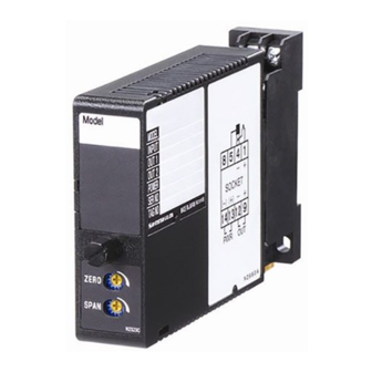
Super-mini Signal Conditioners Mini-M Series
TACHOGENERATOR TRANSMITTER
Functions & Features
• Converts an AC voltage from a tachogenerator
(tachometer) into a standard process signal
• Wide input range
• CE marking
• UL approval
Typical Applications
• Measuring rotating or moving speed of multispeed
motors, belt conveyers, metering pumps
23 (.91)
76
(2.99)
124
(4.88)
mm (inch)
MODEL: M2TG-[1][2]-[3][4]
ORDERING INFORMATION
• Code number: M2TG-[1][2]-[3][4]
Specify a code from below for each [1] through [4].
(e.g. M2TG-AA-M2/CE/Q)
• Special input and output ranges (For codes U, Z&0)
• Specify the specification for option code /Q
(e.g. /C01/S01)
[1] INPUT
Voltage
1: 0 – 35 V AC (Input resistance 100 kΩ min.)
2: 0 – 50 mV AC (Input resistance 100 kΩ min.)
3: 0 – 60 mV AC (Input resistance 100 kΩ min.)
4: 0 – 100 mV AC (Input resistance 100 kΩ min.)
5: 0 – 1 V AC (Input resistance 100 kΩ min.)
6: 0 – 10 V AC (Input resistance 100 kΩ min.)
7: 0 – 100 V AC (Input resistance 100 kΩ min.)
8: 0 – 110 V AC (Input resistance 100 kΩ min.)
9: 0 – 150 V AC (Input resistance 100 kΩ min.)
A: 0 – 200 V AC (Input resistance 100 kΩ min.)
B: 0 – 250 V AC (Input resistance 100 kΩ min.)
U: Specify voltage (0 % input must be 0 V.)
SEN TRONIC
AG
Produkte, Support und Service
[2] OUTPUT
Current
A: 4 – 20 mA DC (Load resistance 750 Ω max.)
B: 2 – 10 mA DC (Load resistance 1500 Ω max.)
C: 1 – 5 mA DC (Load resistance 3000 Ω max.)
D: 0 – 20 mA DC (Load resistance 750 Ω max.)
E: 0 – 16 mA DC (Load resistance 900 Ω max.)
F: 0 – 10 mA DC (Load resistance 1500 Ω max.)
G: 0 – 1 mA DC (Load resistance 15 kΩ max.)
Z: Specify current (See OUTPUT SPECIFICATIONS)
Voltage
1: 0 – 10 mV DC (Load resistance 10 kΩ min.)
2: 0 – 100 mV DC (Load resistance 100 kΩ min.)
3: 0 – 1 V DC (Load resistance 1000 Ω min.)
4: 0 – 10 V DC (Load resistance 10 kΩ min.)
5: 0 – 5 V DC (Load resistance 5000 Ω min.)
6: 1 – 5 V DC (Load resistance 5000 Ω min.)
4W: -10 – +10 V DC (Load resistance 10 kΩ min.)
5W: -5 – +5 V DC (Load resistance 5000 Ω min.)
0: Specify voltage (See OUTPUT SPECIFICATIONS)
[3] POWER INPUT
AC Power
M: 85 – 264 V AC (Operational voltage range 85 – 264 V,
47 – 66 Hz)
(Select '/N' for 'Standards & Approvals' code.)
M2: 100 – 240 V AC (Operational voltage range 85 – 264 V,
47 – 66 Hz)
(90 – 264 V for UL)
DC Power
R: 24 V DC
(Operational voltage range 24 V ±10 %, ripple 10 %p-p max.)
R2: 11 – 27 V DC
(Operational voltage range 11 – 27 V, ripple 10 %p-p max.)
(Select '/N' for 'Standards & Approvals' code.)
P: 110 V DC
(Operational voltage range 85 – 150 V, ripple 10 %p-p max.)
(110 V ±10 % for UL)
[4] OPTIONS (multiple selections)
STANDARDS & APPROVALS (must be specified)
/N: Without CE or UL
/CE: CE marking
/UL: UL approval (CE marking)
OTHER OPTIONS
blank: none
/Q: Option other than the above (specify the specification)
(UL not available)
Rugghölzli 2
Tel. +41 (0)56 222 38 18
CH - 5453 Busslingen
Fax +41 (0)56 222 10 12
MODEL: M2TG
mailbox@sentronic.com
www.sentronic.com
Advertisement
Table of Contents

Related Manuals for M-system Mini-M M2TG-14-M2


Summary of Contents for M-system Mini-M M2TG-14-M2
- Page 1 MODEL: M2TG [2] OUTPUT Super-mini Signal Conditioners Mini-M Series Current A: 4 – 20 mA DC (Load resistance 750 Ω max.) TACHOGENERATOR TRANSMITTER B: 2 – 10 mA DC (Load resistance 1500 Ω max.) Functions & Features C: 1 – 5 mA DC (Load resistance 3000 Ω max.) •...
- Page 2 Line voltage effect: ±0.1 % over voltage range SPECIFICATIONS OF OPTION: Q (multiple selections) Insulation resistance: ≥ 100 MΩ with 500 V DC COATING (For the detail, refer to M-System's web site.) Dielectric strength: 2000 V AC @1 minute (input to output /C01: Silicone coating...
- Page 3 MODEL: M2TG DIMENSIONS unit: mm (inch) 6 (.23) DIN RAIL 35mm wide 2–4.2x5 (.17x.20) MTG HOLE 6 (.24) deep 8–M3 SCREW 14 13 21.5 (.85) 10 (.39) 84 (3.31) 15 (.59) 114 (4.49) [4 (.16)] 23 (.91) • When mounting, no extra space is needed between units. SCHEMATIC CIRCUITRY &...
- Page 4 • Indoor use • When heavy dust or metal particles are present in the air, Thank you for choosing M-System. Before use, please check install the unit inside proper housing with sufficient ven- contents of the package you received as outlined below.
- Page 5 M-System’s option, the repair, replacement or refund of the purchase price of any M-System product which is defective under the terms of this warranty. To submit a claim under this warranty, the purchaser must return, at its expense, the defective M-System product to the below address together with a copy of its original sales invoice.
Need help?
Do you have a question about the Mini-M M2TG-14-M2 and is the answer not in the manual?
Questions and answers