Advertisement
Quick Links
INSTRUCTION MANUAL
PARAMETER GENERATOR
BEFORE USE ....
Thank you for choosing M-System. Before use, please check
contents of the package you received as outlined below.
If you have any problems or questions with the product,
please contact M-System's Sales Office or representatives.
■ PACKAGE INCLUDES:
Signal conditioner (body + base socket) .............................(1)
■ MODEL NO.
Confirm Model No. marking on the product to be exactly
what you ordered.
■ INSTRUCTION MANUAL
This manual describes necessary points of caution when
you use this product, including installation, connection and
basic maintenance procedures.
POINTS OF CAUTION
■ CONFORMITY WITH EU DIRECTIVES
• This equipment is suitable for Pollution Degree 2 and
Installation Category II (transient voltage 2500V). Re-
inforced insulation (output to power input: 300V) is main-
tained. Prior to installation, check that the insulation
class of this unit satisfies the system requirements.
• Altitude up to 2000 meters.
• The equipment must be mounted inside a panel.
• The equipment must be installed such that appropriate
clearance and creepage distances are maintained to con-
form to CE requirements. Failure to observe these re-
quirements may invalidate the CE conformance.
• The actual installation environments such as panel con-
figurations, connected devices, connected wires, may affect
the protection level of this unit when it is integrated in
a panel system. The user may have to review the CE re-
quirements in regard to the whole system and employ ad-
ditional protective measures to ensure the CE conformity.
• Install lightning surge protectors for those wires connect-
ed to remote locations.
■ POWER INPUT RATING & OPERATIONAL RANGE
• Locate the power input rating marked on the product and
confirm its operational range as indicated below:
100 – 240V AC rating: 85 – 264V, 47 – 66 Hz, approx. 3 – 5VA
24V DC rating: 24V ±10%, approx. 3W
11 – 27V DC rating: 11 – 27V, approx. 3W
110V DC rating: 85 – 150V, approx. 3W
■ GENERAL PRECAUTIONS
• Before you remove the unit from its base socket or mount
it, turn off the power supply for safety.
■ ENVIRONMENT
• Indoor use.
• When heavy dust or metal particles are present in the
air, install the unit inside proper housing with sufficient
ventilation.
5-2-55, Minamitsumori, Nishinari-ku, Osaka 557-0063 JAPAN
Phone: +81(6)6659-8201 Fax: +81(6)6659-8510 E-mail: info@m-system.co.jp
MODEL
• Do not install the unit where it is subjected to continuous
vibration. Do not subject the unit to physical impact.
• Environmental temperature must be within -5 to +55°C
(23 to 131°F) with relative humidity within 30 to 90% RH
in order to ensure adequate life span and operation.
• Be sure that the ventilation slits are not covered with ca-
bles, etc.
■ WIRING
• Do not install cables close to noise sources (relay drive
cable, high frequency line, etc.).
• Do not bind these cables together with those in which
noises are present. Do not install them in the same duct.
■ AND ....
• The unit is designed to function as soon as power is sup-
plied, however, a warm up for 10 minutes is required for
satisfying complete performance described in the data
sheet.
• With voltage output, do not leave the output terminals
shortcircuited for a long time. The unit is designed to
endure it without breakdown, however, it may shorten ap-
propriate life duration.
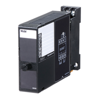
COMPONENT IDENTIFICATION
Body
Fixing Screw
■ FRONT PANEL CONFIGURATION
(A) Polarity Indicator LED
(B) Setpoint Display
(C) Display Selector
Top: ON
Bottom: OFF
(D) UP/DOWN Control
(E) Zero Adj.
(F) Span Adj.
The front cover cannot be turned open by 180 deg.
when there is no extra space between units.
• How to Set an Output
Turn the Display Selector (C) to the top position.
The Setpoint Display (B) shows the current setpoint (-10.0
– +105%). Press UP/DOWN Control (D) until the display
shows a desired set value.
The Polarity Indicator LED (A) is red when the set value is
in positive range, green when in negative range.
The output is factory set to 0%.
Mini-M
™
M2MST
Base Socket
Connection
Diagram
Specifications
EM-5080 Rev.2 P. 1 / 3
Advertisement

Related Manuals for M-system Mini-M M2MST


Summary of Contents for M-system Mini-M M2MST
- Page 1 Do not subject the unit to physical impact. • Environmental temperature must be within -5 to +55°C Thank you for choosing M-System. Before use, please check (23 to 131°F) with relative humidity within 30 to 90% RH contents of the package you received as outlined below.
- Page 2 Applicable wire size: 0.25 to 1.65 mm (AWG 22 to 16) Recommended manufacturer: Japan Solderless Terminal MFG.Co.Ltd, Nichifu Co.,ltd 3.3 (.13) max mm (inch) EM-5080 Rev.2 P. 2 / 3 5-2-55, Minamitsumori, Nishinari-ku, Osaka 557-0063 JAPAN Phone: +81(6)6659-8201 Fax: +81(6)6659-8510 E-mail: info@m-system.co.jp...
- Page 3 “ADJUSTMENT PROCEDURE” explained earlier. LIGHTNING SURGE PROTECTION M-System offers a series of lightning surge protector for protection against induced lightning surges. Please contact M-System to choose appropriate models. EM-5080 Rev.2 P. 3 / 3 5-2-55, Minamitsumori, Nishinari-ku, Osaka 557-0063 JAPAN Phone: +81(6)6659-8201 Fax: +81(6)6659-8510 E-mail: info@m-system.co.jp...
Need help?
Do you have a question about the Mini-M M2MST and is the answer not in the manual?
Questions and answers