
Subscribe to Our Youtube Channel
Related Manuals for Viglen PMPLM001


Summary of Contents for Viglen PMPLM001
- Page 1 Quick Start Guide Viglen Product Description: Intel D945PLM Motherboard Viglen Order Code: PMPLM001 iglen System: Genie (S775) • Product photo Page 1 of 16...
- Page 2 Product specification. Table 1. Motherboard Form Factor Micro ATX (9.60 inches by 9.60 inches [243.84 mm by 243.84 mm]) Motherboard chipset Intel® 945P Chipset CPU connector type (s370, LGA775 socket slot1 etc) Number of CPUs supported Supported CPU types Pentium D, Pentium 4 and Celeron Supported CPU speeds CPU No.
- Page 3 Make sure you are earthed and free of static charge before you open the computer case. If you are unsure about upgrading your computer, return it to Viglen so a qualified engineer can perform the upgrade. Page 3 of 16...
- Page 4 STEPS TO TAKE TO PREVENT STATIC DISCHARGE: 1. The best way to prevent static discharge is to buy an anti-static strap from your local electrical shop. While you are wearing the strap and it is earthed, static charge will be harmlessly bled to ground.
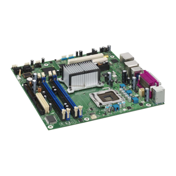
- Page 5 • System Board Components E F G Intel 82945G Intel 82945P GMCH Intel 82801G I/O Controller Hub (ICH7) Figure 1 Motherboard Layout & Components Table 2. Sigmatel 9220 audio codec Power connector (24 way ATX2.2) PCI Express x1 bus add-in card connectors Diskette drive connector Front panel audio connector Parallel ATE IDE connector...
- Page 6 • Back Panel Connectors Figure 2. Back Panel Connectors. Table 3. Item Description PS/2* mouse port (Green) PS/2 keyboard port (Purple) Serial port A (Teal) Parallel port (Burgundy) IEE1394a (Optional not fitted) USB ports (two) LAN RJ45 USB ports (two) Audio line out/Retasking Port D (Lime Green) Mic in / Retasking Port B (Pink)
- Page 7 • Front panel connections The following are all connectors situated along the front edge of the motherboard. They are often connected to buttons and LED’s situated on the front panel. Figure 3. Front panel connectors A- Hard Disk L.E.D. Connector This goes to the Hard Disk L.E.D.
- Page 8 • Motherboard Connectors There are connectors on the motherboard for FAN, IDE, Power supply, CD audio, Floppy, IDE, & Front Panel Connectors. The location and/or details of these connections are shown below. Front Panel Audio Rear Chassis FRONT IEE1394a HEADER Intel 82945G Intel 82945P GMCH...
- Page 9 • Jumper settings CAUTION Do not move any jumpers with the power on. Always turn off the power and unplug the power cord from the computer before changing a jumper setting. Otherwise, the board could be damaged. Intel 82945P Intel 82801G I/O Controller Hub (ICH7)
-
Page 10: System Memory
System Memory The boards have four DIMM sockets and support the following memory features: • 1.8 V DDR2 SDRAM DIMMs with gold-plated contacts • Unbuffered, single-sided or double-sided DIMMs with the following restriction: Double-sided DIMMS with x16 organization are not supported. •... - Page 11 Memory Configurations • The Intel 82945P MCH supports two types of memory organization: • Dual channel (Interleaved) mode. This mode offers the highest throughput for real world applications. Dual channel mode is enabled when the installed memory capacities of both DIMM channels are equal.
- Page 12 Dual Channel (Interleaved) Mode Configurations Figure 7 shows a dual channel configuration using two DIMMs. In this example, the DIMM0 (blue) sockets of both channels are populated with identical DIMMs. Figure 7. Dual Channel (Interleaved) Mode Configuration with Two DIMMs Figure 8 shows a dual channel configuration using three DIMMs.
- Page 13 Single Channel (Asymmetric) Mode Configurations NOTE Dual channel (Interleaved) mode configurations provide the highest memory throughput. Figure 10 shows a single channel configuration using one DIMM. In this example, only the DIMM0 (blue) socket of Channel A is populated. Channel B is not populated. Figure 10.
- Page 14 Installing & Removing DDR2 SDRAM In-line Memory Modules (DIMMs) Installing Memory You can install from 128MB to 4GB of memory in the motherboard DIMM sockets. The board has four 240-pin DDR2 SDRAM DIMM sockets. The motherboard supports the following memory features: •...
-
Page 15: Removing Memory
Removing Memory To remove a DIMM, follow these steps: 1. Observe the precautions in " Upgrading and ESD precautions”. 2. Turn off all peripheral devices connected to the computer. Turn off the computer. 3. Remove the computer cover. 4. Gently spread the retaining clips at each end of the socket. The DIMM pops out of the socket. - Page 16 BIOS Initial Release. SN94510J.86A.0044 Drivers initial release Windows 98SE, Windows ME, Windows NT4 Drivers are all not supported Windows 2000 Drivers Audio: Sigmatel 9220/9221 5.10.4455.0 4.16 MB 10 May 2005 INF: Intel® Chipset Software Installation 7.0.0.1025 789 KB 27 May 2005 Utility LAN: Intel®...
Need help?
Do you have a question about the PMPLM001 and is the answer not in the manual?
Questions and answers