
Related Manuals for Viglen PMPGF001


Summary of Contents for Viglen PMPGF001
- Page 1 Viglen Limited Quick Start Guide Viglen Product Description: Intel D965GF Motherboard Viglen order Code: PMPGF001 Viglen System: Genie (S775) Product Photograph: Page - 1 - of 21...
-
Page 2: Product Specification
Product Specification microATX (243.84 millimeters [9.60 inches] x 243.84 millimeters Motherboard Form Factor [9.60 inches]) Intel® Q965 Express Chipset consisting of: Motherboard chipset • Intel® 82G965 Graphics Memory Controller Hub (GMCH) • Intel® 82801HB I/O Controller Hub (ICH8) LGA 775 CPU connector type (s370, slot1 etc) Number of CPUs supported... - Page 3 Yes via PCI Audio Upgradeable? Gigabit (10/100/1000 Mbits/sec) LAN subsystem using the Onboard network fitted? Intel® 82566DM Gigabit Ethernet Controller Type Intel® Active Management Technology (Intel® AMT) with System Defence Feature Number of network connections? Yes via PCI Upgradeable? Onboard SCSI fitted? Type No of channels? Manufacturer? Model Number?
- Page 4 Supported CPU List in Detail See the table below for a complete list of supported processors. Processor Processor Processor System Bus L2 Cache Size Family Number Speed Frequency E6700 2.66 GHz 1066 MHz 4 MB E6600 2.40 GHz 1066 MHz 4 MB E6400 2.13 GHz...
- Page 5 3.06 GHz 533 MHz 256 KB 345J 3.06 GHz 533 MHz 256 KB 2.93 GHz 533 MHz 256 KB 340J 2.93 GHz 533 MHz 256 KB Intel® 2.80 GHz 533 MHz 256 KB Celeron® D Page - 5 - of 21...
- Page 6 The wire which is coloured brown must be connected to the terminal which is marked with the letter L or coloured red. Make sure you are earthed and free of static charge before you open the computer case. If you are unsure about upgrading your computer, return it to Viglen so a qualified engineer can perform the upgrade. CAUTION!
- Page 7 STEPS TO TAKE TO PREVENT STATIC DISCHARGE: 1. The best way to prevent static discharge is to buy an anti-static strap from your local electrical shop. While you are wearing the strap and it is earthed, static charge will be harmlessly bled to ground. 2.
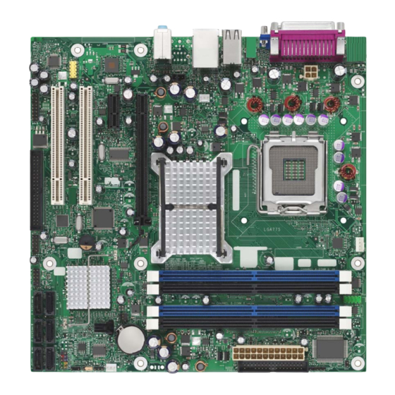
- Page 8 • System Board Components Figure 1 - Motherboard Layout & Components Table 1 Item Description Item Description Front panel audio header (HD or AC97) Battery PCI Conventional bus add-in card Front chassis fan header connector 1 PCI Express x1 connector Chassis intrusion header PCI Express x16 connector Intel 82801HO I/O Controller Hub...
- Page 9 • Back Panel Connectors 5.1 SigmaTel audio STAC9227 The Motherboard external IO connectors are attached to a metallic I/O shield. This shield serves several purposes: • It protects the sensitive Motherboard from any external EMC interference. • It stops the computer from interfering with other electrical devices. •...
- Page 10 • Internal headers There are connector headers on the motherboard for Front Panel, Alternative front panel Power LED, USB1/USB2, HD Audio Link, Audio and Serial connector headers. The location and or details of these internal headers are shown below (Figure 3). Figure 3 - Internal Headers Table 3 Item...
-
Page 11: Front Panel Connections
• Front Panel connections The following are all connectors situated along the front edge of the motherboard. They are often connected to buttons and LED’s situated on the front panel. Figure 4 – Front Panel Connectors Table 4 Connector Comments HD LED This goes to the Hard Disk L.E.D. -
Page 12: Jumper Settings
• Jumper settings CAUTION: Do not move any jumpers with the power on. Always turn off the power and unplug the power cord from the computer before changing a jumper setting. Otherwise, the board could be damaged. Figure 5 - Location of the BIOS Configuration Jumper Block The three-pin BIOS jumper block enables all board configurations to be done in the BIOS Setup program. -
Page 13: System Memory
System Memory The board has four DIMM sockets and supports the following memory features: 1.8 V (only) DDR2 SDRAM DIMMs with gold-plated contacts • Unbuffered, single-sided or double-sided DIMMs with the following • restriction: Double-sided DIMMS with x16 organization are not supported. 8 GB maximum total system memory using DDR2 667 or DDR2 •... - Page 14 NOTE: Regardless of the DIMM type used, the memory frequency will either be equal to or less than the processor system bus frequency. For example, if DDR2 800 memory is used with a 533 MHz system bus frequency processor, the memory will operate at 533 MHz. Table 14 lists the resulting operating memory frequencies based on the combination of DIMMs and processors.
- Page 15 NOTE: The DIMM0 sockets of both channels are blue. The DIMM1 sockets of both channels are black. Figure 6 - Memory Channel Configuration and DIMM Configuration NOTE: Regardless of the memory configuration used (dual channel, single channel, or flex mode), DIMM 0 of Channel A must always be populated. This is a requirement of the ICH8 Manageability Engine feature.
- Page 16 NOTE: The Intel Management Engine in the chipset requires memory to be populated in Channel A, DIMM 0 in order for it to enable Intel Quiet System Technology and Intel Active Management Technology. Figure 8 shows a dual channel configuration using three DIMMs. In this example, the combined capacity of the two DIMMs in Channel A equal the capacity of the single DIMM in the DIMM0 (blue) socket of Channel B.
- Page 17 Single Channel (Asymmetric) Mode Configurations NOTE: Dual channel (Interleaved) mode configurations provide the highest memory throughput. Figure 10 - shows a single channel configuration using one DIMM. In this example, only the DIMM0 (blue) socket of Channel A is populated. Channel B is not populated. Figure 10 - Single Channel (Asymmetric) Mode Configuration with One DIMM Figure 11- shows a single channel configuration using three DIMMs.
- Page 18 Figure 12 - Flex Mode Configuration with Two DIMMs • Installing and Removing Memory CAUTION: When connected to AC power, the memory slots on the board will be powered and in use. A red LED (Figure 13) - B, located near the memory slots, will be lit if the memory slots are powered.
- Page 19 • Installing DIMMs To install a DIMM, follow these steps: 1) Turn off all peripheral devices connected to the computer. Turn off the computer and disconnect the AC power cord. 2) Make sure the clips at either end of the DIMM socket(s) are pushed outward to the open position (see Figure 14)-A.
- Page 20 • Removing DIMMs To remove a DIMM, follow these steps: 1) Turn off all peripheral devices connected to the computer. Turn off the computer. 2) Remove the AC power cord from the computer. 3) Remove the computer’s cover. 4) Gently spread the retaining clips at each end of the DIMM socket. The DIMM pops out of the socket.
- Page 21 TPM and configures all security passwords. End user will also need to install the Trusted Platform module software (TPM_ST_Micro). This can be found under C:\Utils\Onboard directory of the system hard disk drive or from Driver CD or Viglen FTP site. All the above drivers are PC99 certified.
Need help?
Do you have a question about the PMPGF001 and is the answer not in the manual?
Questions and answers