Table of Contents
Advertisement
Quick Links
Advertisement
Table of Contents

Related Manuals for Nauticam NA-A6500


Summary of Contents for Nauticam NA-A6500
- Page 2 ORWARD Thank you for your purchase of a NAUTICAM housing. At NAUTICAM, we pride ourselves in the ability to recognise the requirements of professional as well as amateur underwater photographers and fulfill them through the innovative designs of our products. We strive to achieve a high level of user-friendliness by allowing stress-free installation and easy operation of all important functions of the camera.
-
Page 3: Table Of Contents
ABLE OF ONTENTS Warranty ……………………………………………………………………………………………………………. Precautions ………………………………………………………………………………………………………… Package Contents ………………………………………………………………………………………………. Specifications …………………………………………………………………………………………………….. Identification of Parts ………………………………………………………………………………………… Opening and Locking the Housing ……………………………………………………………………… Preparation of the Housing ………………………………………………………………………………… Installing the Camera …………………………………………………………………………………………. Switching between Viewfinder and Monitor ……………………………………………………… Mounting the Port ……………………………………………………………………………………………… Changing the Viewfinder ……………………………………………………………………………………. -
Page 4: Warranty
NAUTICAM does not hold responsibility for damage, of any nature, to any equipment used with and/or placed within our products. NAUTICAM accepts no liability for any loss of captured images or the inability to capture images even if it is due to the malfunctioning of our products. -
Page 5: Precautions
O-ring(s). • Do not use lubricants from other brands with the silicone rubber O-ring on this housing, only use the lubricant provided by NAUTICAM. • Discontinue use immediately should you notice any leakage. - Page 6 • Do not open the product in a wet or sandy environment. Protect the interior from moisture and debris in order to prevent malfunction or leakage. • Do not store the product in an environment of high humidity. • Do not leave the housing and the monitor in direct sunlight for prolonged periods. •...
-
Page 7: Package Contents
ACKAGE ONTENTS • NA-A6500 housing • Spare silicone rubber O-ring for housing • O-ring remover • CR2032 battery • Lubricant • Set of Allen keys • Instruction manual... -
Page 8: Specifications
PECIFICATIONS Housing body: Aluminium alloy Construction Surface treatment: Hard anodised Display window: Abrasion resistant polycarbonate Width: 306mm Dimensions Height: 168mm Depth: 100mm Weight Approx. 1.56kg Buoyancy Slightly negative Depth rating 100 metres Port mount Compatible Sony α6500 camera cameras... -
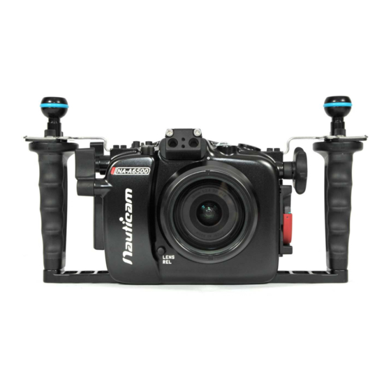
Page 9: Identification Of Parts
DENTIFICATION OF ARTS M10 strobe mounting base Moisture alarm window Accessory coldshoe M16 accessory port Zoom/Focus knob On/off lever Shutter release lever Optical fibre mount Port alignment index Lens release button Port release safety button Port lock/release lever... - Page 10 C2 button Rear control dial C1 button Mode dial AF/MF / AEL lever M14 accessory port Flash up/off lever 0.66x viewfinder Housing lock safety button Housing lock...
- Page 11 AF/MF / AEL switch lever Menu button Fn button VF/LCD lever Movie button Up / Display button Control wheel Left / Drive mode button Right / ISO button Center button Down / Exposure comp. / Image index button C3 / Delete button Playback button...
-
Page 12: Opening And Locking The Housing
PENING AND OCKING THE OUSING To open the housing: Press the housing lock safety Turn the housing lock anti- button. clockwise for 270°, until the lock reaches the “Open” position as shown... - Page 13 To lock the housing: Close the housing while the 2. Turn the housing lock clockwise housing is in the “Open” position. for 270°, until the lock reaches the “lock” position as shown. Confirm that the white indicator line on the safety button is visible.
-
Page 14: Preparation Of The Housing
Prepar REPARATION OF THE OUSING 1. After verifying that the main O-ring is in 4. Setting up the moisture alarm: good condition, lightly coat it with the lubricant provided. 2. Make sure the O-ring groove located in the front part of the housing is free from any foreign material;... - Page 15 2. Switch the alarm on. The LED 3. Test the alarm by connecting the light will flash blue once and turn two wires near the bottom of the blue for five seconds indicating housing with a damp cotton bud; the battery is normal. Then it the alarm should start giving out goes into flashing blue light a repeating “beep”...
- Page 16 Optional vacuum valve: Vacuum valve can be attached to the housing via one of the accessory port for conducting a vacuum seal test. Please refer to the manual of the vacuum valve for details of the operation. LED status identification: On start up LED indicator Status...
- Page 17 After start up LED indicator Status Standby mode. The moisture alarm is active, Flashing "Blue" light and the system is ready for vacuum indication whenever a vacuum is detected. Flashing "Red" light Moisture is detected. with beeping sound Some vacuum is detected, target vacuum level Flashing "Yellow"...
-
Page 18: Installing The Camera
NSTALLING THE AMERA To install the camera into to the housing: 1. Disengage camera 2. Tilt the LCD monitor* of the saddle locks by pressing them camera upwards, then attach inwards. Remove the camera the saddle to the camera by saddle from the housing by tightening the screw to the sliding it outwards. - Page 19 3. Please make sure the eyepiece 4. Install the camera by sliding the cup is not attached to the attached saddle along the rail in camera. the housing until it cannot go in any further. Confirm that the red camera saddle locks are in the engaged position before closing the housing.
-
Page 20: Switching Between Viewfinder And Monitor
Connect WITCHING BETWEEN IEWFINDER AND ONITOR By default, auto switching between the viewfinder and monitor is disabled when the monitor is tilted, and the monitor will always on. This will also affect the function of VF/LCD lever on the housing. We recommend the two methods below for user who require to switch bwtween viewfinder and monior. - Page 21 Connect 2) Install the camera without tilting the monitor: Remove the LCD monitor support After attached the camera tray, from the camera sadle before position the monitor as close as attaching it to the camera. to the camera body. Set the “Viewfinder/Monitor” switch to “Auto” from camera menu, the display can be switched between viewfinder and monitor with the housing’s VF/LCD lever.
-
Page 22: Mounting The Port
Connect OUNTING THE Please refer to the NAUTICAM system port chart for a range of compatible ports: 1. Remove the O-ring from the port, inspect for any damage and lightly coat it with the provided lubricant before placing it back into its groove. - Page 23 Connect 4. Turn the port locking lever to 5. Lift housing cap. the release position as shown.
- Page 24 Connect 6. Align the Port mounting indices 8. Lock the port into place by of the port and the housing. turning the port locking lever to the inward position. To ensure 7. Gently push the port into the that the port is securely port opening of the housing, mounted, confirm that the...
-
Page 25: Changing The Viewfinder
Connect HANGING THE IEWFINDER In order that user can change to a preferred viewfinder easily, the 0.66x viewfinder which comes with the housing is designed so that it can be removed and re-installed by the following simple steps described below. To remove the viewfinder: Push 1. - Page 26 Connect To re-install the viewfinder: Lightly coat the O-rings on the outer periphery of the viewfinder body with lubricant. 2. Push the viewfinder from the 1. Align the viewfinder with the outside of the housing until it sleeve in the display window. cannot go in any further.
-
Page 27: External Battery Pack
XTERNAL ATTERY To extend the battery life of the A6500 camera, an optional battery pack (P.N. 36331) can be mounted inside the housing as an external power source. -
Page 28: Care And Maintenance
O-ring with the provided lubricant before reinstalling it in the groove. A damaged O-ring should be discarded immediately and replaced only with one that is provided by NAUTICAM. • Replace the main O-ring annually. It is recommended that you ship the housing to our... -
Page 29: Optional Accessories
PTIONAL CCESSORIES P.N. 25624 P.N. 32204 P.N. 32205 M14 Vacuum Valve II Nauticam 180˚ straight Nauticam 45˚ viewfinder for (Pushbutton Release) viewfinder for MIL housings MIL housings P.N. 36331 Battery Pack for NA-6500 Housing (2500mAh, inc. USB cable)
Need help?
Do you have a question about the NA-A6500 and is the answer not in the manual?
Questions and answers