Table of Contents
Advertisement
Quick Links
D
Dynamic Motor Motion
Technology Corporation
M M
Type - A General-Purpose Pulse/Analog
Manual Code
Revision
This manual must be kept available for the user
Copyright © 2015 DMM Technology Corp.
DYN2 Series
AC Servo Drive
Specification Manual
: DYN2MS-02F-0116A17
: A1.7
DYN232M
DYN232M
D Y N A C S E R V O S Y S T E M - R S 2 3 2 M O T I O N
adaptive
adaptive
Hardware Version
: AH10
Firmware Version
: AH10
TM
TUNING II
D37
Advertisement
Table of Contents

Related Manuals for DMM DYN232M


Summary of Contents for DMM DYN232M
- Page 1 AC Servo Drive Type - A General-Purpose Pulse/Analog Specification Manual Manual Code : DYN2MS-02F-0116A17 Hardware Version : AH10 Revision : A1.7 Firmware Version : AH10 This manual must be kept available for the user Copyright © 2015 DMM Technology Corp.
-
Page 2: Safety Notice
■ Safety Notice ■ The user or operator should read through this manual completely before installation, testing, operation, or inspection of the equipment. The DYN2 series AC Servo Drive should be operated under correct circum- stances and conditions. Bodily harm or damage to equipment and system may result if specifications outlined in this document are not followed. -
Page 3: Product Manual Preface
Take extra caution at details when the warning convention is used. This manual is available on the DMM Technology Corp. website. A physical copy or reference to the on-line availability must be kept convenient to the servo drive user or operator for references. -
Page 4: Table Of Contents
Manual Contents ■ Safety Notice ■ ■ Notations Used ■ Product Manual Preface Manual Contents Introduction Name Plate Servo Drive Model Number GENERAL SPECIFICATION 1.1 Drive Overall Specification 1.2 Control Block Diagram 1.3 Encoder Specification CONNECTIONS AND WIRING 2.1 DYN2 Servo Drive Body Layout 2.2 Connector and Signal Specification 2.3 JP3 Main I/O Details JP3 I/O Connection Circuit... -
Page 5: Introduction
Lot / Serial Number Hardware / Software Version Servo Drive Model Number D Y N 2 - T L A 6 S - 0 0 0 0 DMM Servo Drive Series Voltage Class DYN2 AC Servo Drive Encoder Model Type... -
Page 6: General Specification
GENERAL SPECIFICATION 1.1 Drive Overall Specification Data Specification Rated Voltage 60VDC ± 10% Input Permissible Input Voltage 24VDC ~ 75VDC Rated Current Peak. +75VAC Rated Voltage Between any two motor phase [L] Capacity Model: Peak. 20A Output Rated Current [1] Capacity Model: Peak 10A From any single motor phase Motor Capacity 50W ~ 750W... -
Page 7: Control Block Diagram
1.2 Control Block Diagram DYN2 AC Servo Drive Main Power Input Main Control Current Sensor Inverter Circuit Current Sensor +15VDC +5VDC Switching Power Supply Isolated Gate Control RS232 Encoder Serial Port Feedback LED S1 Isolated I/O Interface Analog Input Voltage Protection 1.3 Encoder Specification ■... -
Page 8: Connections And Wiring
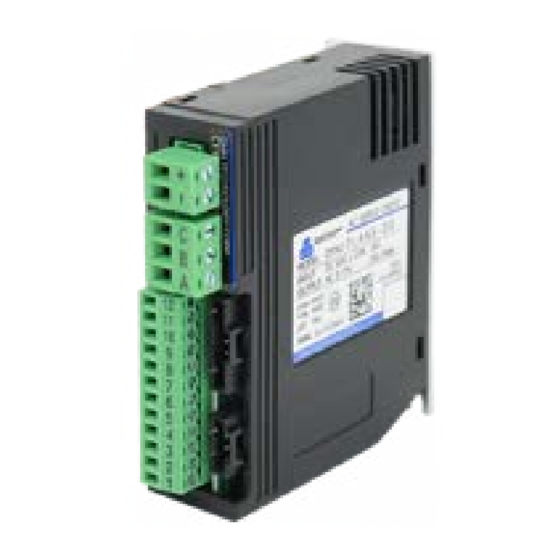
CONNECTIONS AND WIRING 2.1 DYN2 Servo Drive Body Layout ■ JP1 Power Supply Input ■ JP5 Servo Motor Power ■ JP2 RS232 Port to PC ■ JP3 I/O Port ■ S1 Drive Status LED [ Green LED ] ■ JP4 Encoder Feedback Port (1) Drive Body Grounding Terminal [ M3 x 5mm Max. -
Page 9: Connector And Signal Specification
2.2 Connector and Signal Specification ▐ JP1 - Power Supply Input Connector Type: 5.00mm Pitch Terminal Block Drive Header: Phoenix MSTBA 2,5/ 2-G Plug Connector: Phoenix MSTB 2,5/ 2-ST Recommended Wire Gauge: 0.8mm (AWG18) ▐ JP2 RS232 Port to PC Connector Type: 2.54mm Pitch Rectangular Drive Header: Molex 70553-0041 Plug Connector: Molex 50-57-9407... - Page 10 2.2 Connector and Signal Specification ▐ JP4 Encoder Feedback Port Connector Type: 2.54mm Pitch Rectangular Drive Header: Molex 70553-0038 Plug Connector: Molex 50-57-9404 Recommended Wire Gauge: 0.3mm (AWG22) Signal Layout: Pin 1: +5VDC Supply Pin 2: S+ Pin 3: S- Pin 4: Gnd ▐...
- Page 11 2.3 JP3 Main I/O Details WARNING ● Note the directionality of the JP3 connector and pins before making connections. Pin1 is located nearest to the bottom of the servo drive. Pin12 is located nearest terminal JP5 (Servo Motor Power). ■ Terminal Layout DYN2 AC Servo Drive Main Power Input 24 ~ 75VDC...
-
Page 12: Jp3 Main I/O Details
2.3 JP3 Main I/O Details ■ JP3 Signal Specification Refer to Section 2.4 JP3 I/O Connection Circuit for example connection diagram. Standard I/O levels are +5VDC±%10. Contact DMM if the controller uses 12~24VDC level I/O. Pin No. Signal Symbol Type... - Page 13 JP3 Main I/O Details Refer to Section 2.4 JP3 I/O Connection Circuit for example connection diagram. Pin No. Signal Symbol Type OnPosition Output ONPOS Output Description Connection Circuit - Transistor ON (Signal LOW) if servo Off Position. - Transistor OFF (Signal HIGH) if servo On Position. - Servo On Position if motor position error within value set by OnPosRange [ B ] *See section 2.4...
- Page 14 JP3 Main I/O Details Refer to Section 2.4 JP3 I/O Connection Circuit for example connection diagram. Pin No. Signal Symbol Type STEP+, A+, CW+ Pulse Reference STEP+ Input STEP-, A-. CW- Pulse Reference STEP- DIR+, B+. CCW+ Pulse Reference DIR+ DIR-, B-.
-
Page 15: Jp3 I/O Connection Circuit
JP3 I/O Connection Circuit ■ Type [ A ] Connection Circuit - General Input Circuit Applicable Signals: Pin No. Signal Symbol Type Drive Disable Input Input Open Collector Notes: - Sink circuit shown. +5VDC Source circuit can also 270Ω be used. COM 7 Relay/Switch Notes:... - Page 16 JP3 I/O Connection Circuit ■ Type [ B ] Connection Circuit - General Output Circuit Applicable Signals: Pin No. Signal Symbol Type Absolute Zero Position Index Output Output OnPosition Output ONPOS Output Servo Alarm Output Common Collector Output Notes: +5VDC 1kΩ...
- Page 17 JP3 I/O Connection Circuit ■ Type [ C ] Connection Circuit - Position Reference Pulse Input Applicable Signals: Pin No. Signal Symbol Type STEP+, A+, CW+ Pulse Reference STEP+ Input STEP-, A-. CW- Pulse Reference STEP- DIR+, B+. CCW+ Pulse Reference DIR+ DIR-, B-.
- Page 18 JP3 I/O Connection Circuit ■ Type [ D ] Connection Circuit - Analog Command Reference Input Applicable Signals: Pin No. Signal Symbol Type Analog Command Reference AGIN Input Ground Notes: - Twisted pair cable with shield grounded on receiver side. AGIN D/A Converter Op-amp...
- Page 19 Main Power Supply Requirements The DYN2 servo drive has a minimum operation input of +24VDC and max input of +75VDC. The servo drives internal over-voltage alarm is triggered at +80VDC input and will shut down at this level. Consider the voltage/speed gradient of the servo motor when selecting power supplies. A smoothing (reservoir) capacitor is recommended after the DC power supply.
- Page 20 ■ Regenerative Circuit An external regenerative circuit may be needed for applications with high load inertia deceleration. Con- tact DMM for DYN2 regenerative circuit requirements. DC Power Supply External Regen. Resistor Regenerative Circuit DYN2 Servo Drive DYN2 Servo Drive DYN2 Servo Drive...
- Page 21 The control cabinet internal temperature should not exceed 40°C. If using a fan to cool the servo drives, the air flow should parallel the direction of the heat sink fin. The servo drive internally do not have a cool- ing fan. Contact DMM if servo drives need to be placed adjacent without spacing. >1mm >1mm...
- Page 22 3.2 Timing Chart ■ Power ON Timing After servo drive power ON, make sure there is at least 150ms time before sending pulse or analog com- mand to servo drive. 50ms Main Power Supply Status LED lit Green S1 Status LED 100ms Servo ON (Motor Servo Lock)
- Page 23 3.2 Timing Chart ■ Servo Disable / Enable Timing When using the ENA signal to disable the servo drive to coast the servo motor, do not cycle this input rapidly ON/OFF. If the signal is cycled too fast, the servo drive will not have enough time to initialize the control program during Enable and can cause unwanted or dangerous results.
- Page 24 3.3 DMMDRV Software Communication ■ Version 1.0 ♦ PC Running Requirements Win98/XP/2000/Vista/7 250Mhz CPU 64MB RAM 250MB Hard Disk Space The servo drive should be powered up with the servo motor encoder feedback and motor power cables connected. The servo motor shaft will be servo-locked when powered ON. Connect the RS232 tuning cable from port JP2 to host PC.
- Page 25 3.3 DMMDRV Software Communication ■ Version 328.1 ♦ PC Requirements Operating System: Windows XP SP3 or higher *Recommended: Windows 7 (32-bit / 64-bit) Processor: Pentium 1 GHz or higher RAM: 512 MB or more Framework: .NET Framework 4 or higher Minimum disk space: 60MB *See User Manual DSFEN for complete instructions: DYN2MS-02F-0116A17...
- Page 26 OPERATION 4.1 Position Servo Mode █ Pulse Specifications Voltage: +5VDC ± %10 (Contact DMM if higher level such as 12/24VDC is required) Max pulse frequency: 500kHz Minimum pulse width: 0.8μs ♦ Pulse + Direction t1, t4 ≥ 0.8μs t2, t3 ≤ 1.0μs t5, t6 ≥...
- Page 27 4.1 Position Servo Mode █ Reference Pulse Format The DYN2 servo drive accepts FORWARD reference as CLOCKWISE motor shaft rotation as viewed from motor shaft side. ♦ Pulse + Direction Forward Reference Reverse Reference PUL+ PUL+ JP3-6 JP3-6 DIR+ DIR+ JP3-4 JP3-4 ♦...
- Page 28 4.1 Position Servo Mode █ Connection Example ♦ Line Drive Output 270Ω PUL+, A+, CW+ PUL-, A-, CW- 270Ω DIR+, B+, CCW+ DIR-, B-, CCW- ♦ Open Collector Output - Internal Power Supply +5VDC 270Ω PUL+, A+, CW+ PUL-, A-, CW- 270Ω...
- Page 29 4.1 Position Servo Mode █ Electronic Gearing ( GEAR_NUM Parameter ) Gear number is set from 500 to 16,384, default value is 4,096. Gear number provides an electrical gear ratio: 4096 / Gear_Num, from 0.25 ~ 8.192. For example, if Gear number = 4,096, the 16,384 input counts from pulse will turn motor exactly one revolution.
- Page 30 4.2 Speed Servo Mode In speed servo mode, the DYN2 servo drive takes command from an external ±10VDC analog reference voltage from the host controller to drive a linear proportional motor speed. In speed servo mode, the torque output depends on the load on the servo motor and determined by the motor feedback.
- Page 31 4.2 Speed Servo Mode █ Acceleration / Deceleration Soft Start In Speed Servo Mode, the Max Acceleration parameter in the servo drive can be used to soft start/stop the servo motor. Since the speed command is sent as a rough step reference, it is often desirable to smooth out the servo motor’s movement dynamics.
- Page 32 4.3 Torque Servo Mode In torque servo mode, the DYN2 servo drive takes command from an external ±10VDC analog reference voltage from the host controller to drive a linear proportional output current. █ Control Reference - [ 1 ] Capacity Model: DYN2-T1 The DYN2 servo drive accepts FORWARD reference as CLOCKWISE motor shaft rotation as viewed from motor shaft side.
- Page 33 4.4 RS232 Command Input Mode The RS232 port is always active after power on for DYN-series servo drive, that active RS232 port could be used for reading and setting Drive parameters and status, also could be used for sending point to point position command if the RS232 mode is selected for position command input.
- Page 34 PARAMETERS AND TUNING 5.1 Parameters Outline The following parameters are adjustable by connection through RS232 or USB interface from the servo drive to the PC. No matter the command mode, the JP2 RS232 port is always active for parameter setting and drive configuration.
- Page 35 5.1 Parameters Outline Applicable Servo Parameter Name Setting Range Details Mode Determine the S-curve acceleration when using RS232 RS232 mode to make point to point motion linear/circular. Also Max Acceleration [ 1 : 127 ] Speed controls the response time of the first order low pass filter Torque in speed and torque servo control (soft start).
- Page 36 adaptive adaptive TUNING II 5.2 Servo Drive Gain Tuning The DYN2 servo drive features simple 3 parameter Gain tuning to achieve optimized smooth performance. The user should adjust the servo gain parameters Main Gain, Speed Gain and Integration Gain until they achieve target response qualities.
- Page 37 5.2 Servo Drive Gain Tuning █ Sample Load Type Tunings ♦ Ball Screw Ball screw systems are mechanically very rigid and stiff. If high resolution pitch (e.g. 5mm or 10mm) the default setting could even be used. The servo drive can be easily tuned using Main Gain, Speed Gain, and Integration Gain.
- Page 38 MAINTENANCE 6.1 Alarm Specifications The DYN2 servo drive is protected by 5 alarms. The S1 status indicator LED will flash to indicate when an alarm is triggered. The specific alarm status can be read using the DMMDRV program. ♦ Internal Driver Status Readout ( 1 ) Connect the PC to the servo drive JP2 port using RS232 cable ( 2 )
- Page 39 6.2 - Drive Maintenance Do not perform maintenance on the servo drive unless instructed to do so by DMM. The servo drive cover or chassis should never be removed as high voltage components can cause electric short, shock or other damage upon contact.
- Page 40 RS232 mode is selected for position command input. This DYN232M integrated motion command includes point-to-point S-curve, linear, arc and circular interpolation for up to 3-axis of coordinated motion. These profiles can be easily executed using dedicated function codes.
- Page 41 DTPU DYN232M DYN232M 7.1 Interface and Format P O S I T I O N I N G D Y N A C S E R V O S Y S T E M - R S 2 3 2 M O T I O N █...
- Page 42 7.1 Interface and Format █ Transmission The DYN servo drive is always under command from host controller. When a function is called, the servo drive will move the servo motor, return a data packet with the requested information, or set a parameter value. Once a complete data packet has been received, the servo drive will not return any confirmation or acknowledgement code.
- Page 43 DTPU DYN232M DYN232M 7.2 Packet Definition P O S I T I O N I N G D Y N A C S E R V O S Y S T E M - R S 2 3 2 M O T I O N 7.2.1 Structure...
- Page 44 7.2 Packet Definition 7.2.4 Bn-1 byte The Bn-1 byte is used for representing the packet function and packet length. Bn-1 = 1 b6 b5 b4 b3 b2 b1 b0 The bit b6 and b5 are for the length of packet, expressed as: Total packet length(=n+1) The bit b4~b0 are used for the packet function, expressed as: Function (Sent by host)
- Page 45 7.2 Packet Definition Functions (Sent by DYN drive) b[4:0] Data (Bytes) Remarks Not used 0x00 ~ *Do not read or write to these addresses 0x0a Is_MainGain 0x10 Returns [1:127] unsigned data Is_SpeedGain 0x11 Returns [1:127] unsigned data Is_IntGain 0x12 Returns [1:127] unsigned data Is_TrqCons 0x13 Returns [1:127] unsigned data...
- Page 46 7.2 Packet Definition 7.2.6 B0 Byte B0 byte is used for check sum, which is calculated from Bn~B1 as: S = Bn + Bn-1 + Bn-2 +..B1 B0 = 0x80 + Mod(S , 128), B0 = 0x80 + S - 128*[S/128] B0 = 128 ~ 255 After receiving a packet, then calculate Temp = Mod(S , 128), if Temp = B0 , there is no error, otherwise there is error during the packet transmission.
- Page 47 DTPU DYN232M DYN232M 7.3 Drive Configuration and Status Register P O S I T I O N I N G D Y N A C S E R V O S Y S T E M - R S 2 3 2 M O T I O N Drive configuration such as command input mode (RS232, CW/CCW etc.), alarm status, busy status are de-...
- Page 48 DTPU DYN232M DYN232M 7.4 Common Function Details P O S I T I O N I N G D Y N A C S E R V O S Y S T E M - R S 2 3 2 M O T I O N 7.4.1...
- Page 49 7.4 Common Function Details 7.4.2 Constant Speed, Square Wave, Sin Wave █ Turn Constant Speed Function (Sent by host) b[4:0] Data (Bytes) Turn_ConstSpeed 0x0a The servo motor rotates at constant speed according to the rpm speed set by the Data Bytes. The direction of rotation is CW (as viewed from shaft side) for positive speed and CCW for negative speed.
- Page 50 DTPU DYN232M DYN232M Dynamic Target Position Update ( DTPU ) P O S I T I O N I N G D Y N A C S E R V O S Y S T E M - R S 2 3 2 M O T I O N The DYN servo drives built in S-Curve generator is able to update the target position instantaneously regardless of whether the current command position has completed or not.
- Page 51 Dynamic Target Position Update ( DTPU ) █ Curved Acceleration The DTPU algorithm also applies a curved acceleration to maintain smooth motion. At each S-Curve transition point, the acceleration/deceleration is curved at the edges so speed is smoothly changed. This decreases motor vibration.
- Page 52 DTPU DYN232M DYN232M 7.6 Packet Structure Examples P O S I T I O N I N G D Y N A C S E R V O S Y S T E M - R S 2 3 2 M O T I O N...
- Page 53 DTPU DYN232M DYN232M 7.7 Application Examples P O S I T I O N I N G D Y N A C S E R V O S Y S T E M - R S 2 3 2 M O T I O N ■...
- Page 54 7.7 Application Examples ■ EXAMPLE 4 Condition: Make 3th axis motor move -120(steps) from right now position, ID = 3. Method: -120 = 0x88 = 0xff88 < -63,Two byte data. 0xff88 = 0x1111 1111 1000 1000: Lower 7bits = 000 1000 = 0x08 Higher 7bits = 0111 1111 = 0x7f Use function Go_Relative_Pos(=0x03), Packet Length = 5.
- Page 55 7.7 Application Examples ■ EXAMPLE 7 Condition: Make a line on X-Y Plane Suppose right now position for three motors are(X0,Y0,Z0) = (0,0,0), and the End point of straight line is (X1,Y1,Z1) = (100,200,0) Method: Always use General ID = 0x7f The Feedrate = 3, could be from 1~127 Global_Func = (char)Make_LinearLine = 0x02;...
- Page 56 7.7 Application Examples The following three examples makes use of the sample code in Section 7.7A Appendix : C++ Code for Serial Communication Protocol. All contents of the sample code must be copied to the program. ■ EXAMPLE 9 Condition: Read servo motor absolute position Method: Call ReadMotorPosition32() subroutine function...
- Page 57 DTPU DYN232M DYN232M 7.8 RS485 Serial Network P O S I T I O N I N G D Y N A C S E R V O S Y S T E M - R S 2 3 2 M O T I O N Several Drives can be connected by RS485 after every Drive on the RS485 net have been designated an individ- ual, or broadcasting ID number.
- Page 58 DTPU DYN232M DYN232M 7.9A Appendix : C++ Code for Serial Communication Protocol P O S I T I O N I N G D Y N A C S E R V O S Y S T E M - R S 2 3 2 M O T I O N The following code shows an example to generate a data packet and call functions in RS232 serial protocol.
- Page 59 7.9A Appendix : C++ Code for Serial Communication Protocol void DlgRun::Get_Function(void) char ID, ReceivedFunction_Code, CRC_Check; ID = Read_Package_Buffer[0]&0x7f; ReceivedFunction_Code = Read_Package_Buffer[1]&0x1f; CRC_Check = 0; for(int i=0;i<Comm.Read_Package_Length-1;i++) CRC_Check += Read_Package_Buffer[i]; CRC_Check ^= Read_Package_Buffer[Comm.Read_Package_Length-1]; CRC_Check &= 0x7f; if(CRC_Check!= 0){ //MessageBox(“There is CRC error!”) - Customer code to indicate CRC error else switch(ReceivedFunction_Code){ case Is_AbsPos32:...
- Page 60 7.9A Appendix : C++ Code for Serial Communication Protocol //***************** Every Robot Instruction ****************** // Send a package with a function by Global_Func // Displacement: -2^27 ~ 2^27 - 1 // Note: in the description of RS232 communication protocol above (Section 7), the last byte of packet is always B0, but in the code of below, the first byte is always B0.
- Page 61 7.9A Appendix : C++ Code for Serial Communication Protocol void DlgRun::Make_CRC_Send(unsigned char Plength,unsigned char B[8]) unsigned char Error_Check = 0; for(int i=0;i<Plength-1;i++) OutputBuffer[OutBfTopPointer] = B[i]; OutBfTopPointer++; Error_Check += B[i]; Error_Check = Error_Check|0x80; OutputBuffer[OutBfTopPointer] = Error_Check; OutBfTopPointer++; while(OutBfBtmPointer != OutBfTopPointer) RS232_HardwareShiftRegister = OutputBuffer[OutBfBtmPointer]; SendRS232Port();...
- Page 62 7.9A Appendix : C++ Code for Serial Communication Protocol void DlgRun::ReadMotorPosition32(void) {/*Below are the codes for reading the motor shaft 32bits absolute position */ //Read motor 32bits position char ID = 0; //Suppose read 0 axis motor Global_Func = General_Read; Send_Package(ID , Is_AbsPos32);...
- Page 63 7.9A Appendix : C++ Code for Serial Communication Protocol void main(void) /* (1) Move motor 2 to absolute position of 321,456 - Method 1*/ char Axis_Num = 2; Global_Func = (char)Go_Absolute_Pos; long pos = 321456; Send_Package(Axis_Num,Pos); /* (2) Move motor 2 to absolute position of 321,456 - Method 2 - Using subroutine function*/ MoveMotorToAbsolutePosition32(2,321456);...
- Page 64 7.9A Appendix : C++ Code for Serial Communication Protocol Sample Code Notes: (1) The sample code uses a ring buffer structure to input and output data packet bytes. Two separate ring buffers are using in the code as char InputBuffer[256] and char OutputBuffer[256]. Two position pointers are used in each buffer structure to index the data inside the buffer structure.
- Page 65 APPENDIX A - SERVO DRIVE DIMENSIONS ( Name Plate 1 ) ♦ Exterior Dimensions ( Name Plate 2 ) ( Name Plate 1 ) ( Name Plate 2 ) ( Name Plate 1 ) ( Name Plate 2 ) Chassis Ground Terminal 3 Mount ♦...
- Page 66 APPENDIX B - Operation Examples █ Position Servo Mode - Ball Screw 1. Connect encoder feedback and motor power cable from servo drive to servo motor. 2. Connect RS232 tuning cable from servo drive JP2 to controller PC. 3. Power ON servo drive. 4.
- Page 67 Within the warranty period, DMM Technology Corp. will replace or repair any defective product free of charge given that DMM Technology Corp. is responsible for the cause of the defect. This warranty does not cover cases involving the following conditions: ●...
- Page 68 █ Disclaimer DMM Technology Corp. constantly strive to improve it’s products performance and reliability. The contents of this manual outlines the latest features and specifications of the DYN2 AC Servo Drive and may be changed at any time to reflect corrections, improvements or changes to the product or information in this manual.
- Page 69 Manual Number Electronic Version DYN2MS-02F-0116A17 Revision : A1.7 (D37) Copyright © 2016 DMM Technology Corp. Published In Canada DMM TECHNOLOGY CORP. 120 - 21320 Gordon Way Richmond, British Columbia V6W1J8 Canada PHONE: +1 (604)-370-4168 | FAX: +1 (604) 285-1989 WEB: http://www.dmm-tech.com SALES: sales@dmm-tech.com...
Need help?
Do you have a question about the DYN232M and is the answer not in the manual?
Questions and answers