Table of Contents
Advertisement
D
M M
This manual must be kept available for the user
Copyright © 2014 DMM Technology Corp.
Published In Canada
Dynamic Motor Motion
Technology Corporation
DYN2 Series
AC Servo Drive
Type - A General-Purpose Pulse/Analog
Specification Manual
Manual Code
: DYN2MS-01E-0814A1
Revision
: A1
Hardware Version
: AH10
Firmware Version
: AH10
UNLESS OTHERWISE SPECIFIED:
FINISH:
DIMENSIONS ARE IN MILLIMETERS
SURFACE FINISH:
TOLERANCES:
LINEAR:
ANGULAR:
NAME
SIGNATURE
DATE
DRAWN
CHK'D
APPV'D
MFG
MATERIAL:
Q.A
WEIGHT:
Advertisement
Table of Contents

Subscribe to Our Youtube Channel
Related Manuals for DMM DYN2 Series

Summary of Contents for DMM DYN2 Series
- Page 1 : AH10 UNLESS OTHERWISE SPECIFIED: FINISH: DIMENSIONS ARE IN MILLIMETERS SURFACE FINISH: TOLERANCES: LINEAR: ANGULAR: NAME SIGNATURE DATE DRAWN CHK'D APPV'D MATERIAL: This manual must be kept available for the user Copyright © 2014 DMM Technology Corp. WEIGHT: Published In Canada...
-
Page 2: Safety Notice
The user or operator should read through this manual completely before installation, testing, operation, or inspection of the equipment. The DYN2 series AC Servo Drive should be operated under correct circum- stances and conditions. Bodily harm or damage to equipment and system may result if specifications outlined in this document are not followed. -
Page 3: Product Manual Preface
The user or operator should read through this manual completely before installation, testing, operation, or inspection of the equipment. The DYN2 series AC Servo Drive should be operated under correct circumstances and conditions. Bodily harm or damage to equipment and system may result if spec- ifications outlined in this document are not followed. -
Page 4: Table Of Contents
Manual Contents Safety Notice Notations Used Product Manual Preface Manual Contents A.1 Introduction A.2 Name Plate A.3 Servo Drive Model Number 1 GENERAL SPECIFICATION 1.1 Drive Overall Specification 1.2 Control Block Diagram 1.3 Encoder Specification 2 CONNECTIONS AND WIRING 2.1 DYN2 Servo Drive Body Layout 2.2 Connector and Signal Specification 2.3 JP3 Main I/O Details 2.4 JP3 I/O Connection Circuit... -
Page 5: Introduction
Introduction This manual documents all features and specifications for the DYN2 series AC Servo Drive Type A - General Purpose Pulse/Analog. The servo drive features standard pulse train and analog command input modes compatible with universal motion controllers, PLC’s or CNC controllers. Control modes include po- sition, speed or torque servo mode with standard signal connections and interfacing for seamless integra- tion into any system. -
Page 6: General Specification
GENERAL SPECIFICATION 1.1 Drive Overall Specification Data Specification Rated Voltage 60VDC ± 10% Input Permissible Input Voltage 24VDC ~ 75VDC Rated Current Peak. +75VAC Rated Voltage Between any two motor phase [L] Capacity Model: Peak. 20A Output Rated Current [1] Capacity Model: Peak 10A From any single motor phase Motor Capacity 50W ~ 750W... -
Page 7: Control Block Diagram
1.2 Control Block Diagram DYN2 AC Servo Drive Main Power Input Main Control Current Sensor Inverter Circuit Current Sensor +15VDC +5VDC Switching Power Supply Isolated Gate Control RS232 Encoder Serial Port Feedback LED S1 Isolated I/O Interface Analog Input Voltage Protection 1.3 Encoder Specification ■... -
Page 8: Connections And Wiring
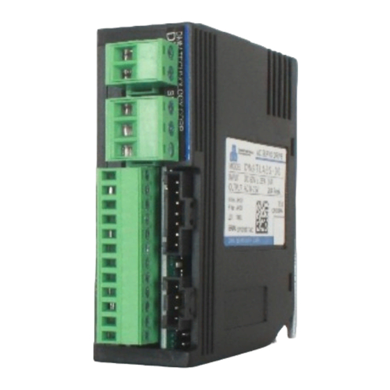
CONNECTIONS AND WIRING 2.1 DYN2 Servo Drive Body Layout ■ JP1 Power Supply Input ■ JP5 Servo Motor Power ■ JP2 RS232 Port to PC ■ JP3 I/O Port ■ S1 Drive Status LED [ Green LED ] ■ JP4 Encoder Feedback Port (1) Drive Body Grounding Terminal [ M3 x 5mm Max. -
Page 9: Connector And Signal Specification
2.2 Connector and Signal Specification ▐ JP1 - Power Supply Input Connector Type: 5.00mm Pitch Terminal Block Drive Header: Phoenix MSTBA 2,5/ 2-G Plug Connector: Phoenix MSTB 2,5/ 2-ST Recommended Wire Gauge: 0.8mm (AWG18) ▐ JP2 RS232 Port to PC Connector Type: 2.54mm Pitch Rectangular Drive Header: Molex 70553-0041 Plug Connector: Molex 50-57-9407... - Page 10 2.2 Connector and Signal Specification ▐ JP4 Encoder Feedback Port Connector Type: 2.54mm Pitch Rectangular Drive Header: Molex 70553-0038 Plug Connector: Molex 50-57-9404 Recommended Wire Gauge: 0.3mm (AWG22) Signal Layout: Pin 1: +5VDC Supply Pin 2: S+ Pin 3: S- Pin 4: Gnd ▐...
-
Page 11: Jp3 Main I/O Details
2.3 JP3 Main I/O Details WARNING ● Note the directionality of the JP3 connector and pins before making connections. Pin1 is located nearest to the bottom of the servo drive. Pin12 is located nearest terminal JP5 (Servo Motor Power). ■ Terminal Layout DYN2 Servo Drive Drive internal +5VDC +5VDC... - Page 12 2.3 JP3 Main I/O Details ■ JP3 Signal Specification Refer to Section 2.4 JP3 I/O Connection Circuit for example connection diagram. Standard I/O levels are +5VDC±%10. Contact DMM if the controller uses 12~24VDC level I/O. Pin No. Signal Symbol Type...
- Page 13 JP3 Main I/O Details Refer to Section 2.4 JP3 I/O Connection Circuit for example connection diagram. Pin No. Signal Symbol Type OnPosition Output ONPOS Output Description Connection Circuit - Transistor ON (Signal LOW) if servo Off Position. - Transistor OFF (Signal HIGH) if servo On Position. - Servo On Position if motor position error within value set by OnPosRange [ B ] *See section 2.4...
- Page 14 JP3 Main I/O Details Refer to Section 2.4 JP3 I/O Connection Circuit for example connection diagram. Pin No. Signal Symbol Type STEP+, A+, CW+ Pulse Reference STEP+ Input STEP-, A-. CW- Pulse Reference STEP- DIR+, B+. CCW+ Pulse Reference DIR+ DIR-, B-.
-
Page 15: Jp3 I/O Connection Circuit
JP3 I/O Connection Circuit ■ Type [ A ] Connection Circuit - General Input Circuit Applicable Signals: Pin No. Signal Symbol Type Drive Disable Input Input Open Collector Notes: - Sink circuit shown. +5VDC Source circuit can also 270Ω be used. COM 7 Relay/Switch Notes:... - Page 16 JP3 I/O Connection Circuit ■ Type [ B ] Connection Circuit - General Output Circuit Applicable Signals: Pin No. Signal Symbol Type Absolute Zero Position Index Output Output OnPosition Output ONPOS Output Servo Alarm Output Common Collector Output Notes: +5VDC 1kΩ...
- Page 17 JP3 I/O Connection Circuit ■ Type [ C ] Connection Circuit - Position Reference Pulse Input Applicable Signals: Pin No. Signal Symbol Type STEP+, A+, CW+ Pulse Reference STEP+ Input STEP-, A-. CW- Pulse Reference STEP- DIR+, B+. CCW+ Pulse Reference DIR+ DIR-, B-.
- Page 18 JP3 I/O Connection Circuit ■ Type [ D ] Connection Circuit - Analog Command Reference Input Applicable Signals: Pin No. Signal Symbol Type Analog Command Reference AGIN Input Ground Notes: - Twisted pair cable with shield grounded on receiver side. AGIN D/A Converter Op-amp...
-
Page 19: Main Power Supply Requirements
Main Power Supply Requirements The DYN2 servo drive has a minimum operation input of +24VDC and max input of +75VDC. The servo drive’s internal over-voltage alarm is triggered at +80VDC input and will shut down at this level. Consider the voltage/speed gradient of the servo motor when selecting power supplies. A smoothing (reservoir) capacitor is recommended after the DC power supply. -
Page 20: Start Up
START UP 3.1 Mounting and Installation The DYN2 servo drive can be mounted vertically or horizontally (vehicle mount). The servo drives should be mounted by its rear chassis to an electrically conductive metal panel or plate. When mounting multiple servo drives, at least 1mm clearance should be left between each unit. The small size of the DYN2 servo drive is compatible with modular mounting. -
Page 21: Timing Chart
3.2 Timing Chart ■ Power ON Timing After servo drive power ON, make sure there is at least 150ms time before sending pulse or analog com- mand to servo drive. 50ms Main Power Supply Status LED lit Green S1 Status LED 100ms Servo ON (Motor Servo Lock) - Page 22 3.2 Timing Chart ■ Servo Disable / Enable Timing When using the ENA signal to disable the servo drive to coast the servo motor, do not cycle this input rapidly ON/OFF. If the signal is cycled too fast, the servo drive will not have enough time to initialize the control program during Enable and can cause unwanted or dangerous results.
-
Page 23: Dmmdrv Software Communication
3.3 DMMDrv Software Communication ♦ PC Running Requirements Win98/XP/2000/Vista/7 250Mhz CPU 64MB RAM 250MB Hard Disk Space The servo drive should be powered up with the servo motor encoder feedback and motor power cables connected. The servo motor shaft will be servo-locked when powered ON. Connect the RS232 tuning cable from port JP2 to host PC. -
Page 24: Operation
OPERATION 4.1 Position Servo Mode █ Pulse Specifications Voltage: +5VDC ± %10 (Contact DMM if higher level such as 12/24VDC is required) Max pulse frequency: 500kHz Minimum pulse width: 800us >800us █ Reference Pulse Format The DYN2 servo drive accepts FORWARD reference as CLOCKWISE motor shaft rotation as viewed from motor shaft side. - Page 25 4.1 Position Servo Mode █ Connection Example ♦ Line Drive Output 270Ω PUL+, A+, CW+ PUL-, A-, CW- 270Ω DIR+, B+, CCW+ DIR-, B-, CCW- ♦ Open Collector Output - Internal Power Supply +5VDC 270Ω PUL+, A+, CW+ PUL-, A-, CW- 270Ω...
- Page 26 4.1 Position Servo Mode █ Electronic Gearing ( GEAR_NUM Parameter ) Gear number is set from 500 to 16,384, default value is 4,096. Gear number provides an electrical gear ratio: 4096 / Gear_Num, from 0.25 ~ 8.192. For example, if Gear number = 4,096, the 16,384 input counts from pulse will turn motor exactly one revolution.
-
Page 27: Speed Servo Mode
4.2 Speed Servo Mode In speed servo mode, the DYN2 servo drive takes command from an external ±10VDC analog reference voltage from the host controller to drive a linear proportional motor speed. In speed servo mode, the torque output depends on the load on the servo motor and determined by the motor feedback. - Page 28 4.2 Speed Servo Mode █ Acceleration / Deceleration Soft Start In Speed Servo Mode, the Max Acceleration parameter in the servo drive can be used to soft start/stop the servo motor. Since the speed command is sent as a rough step reference, it is often desirable to smooth out the servo motor’s movement dynamics.
-
Page 29: Torque Servo Mode
4.3 Torque Servo Mode In torque servo mode, the DYN2 servo drive takes command from an external ±10VDC analog reference voltage from the host controller to drive a linear proportional output current. █ Control Reference - [ 1 ] Capacity Model: DYN2-T1 The DYN2 servo drive accepts FORWARD reference as CLOCKWISE motor shaft rotation as viewed from motor shaft side. -
Page 30: Rs232 Command Input Mode
4.4 RS232 Command Input Mode The RS232 port is always active after power on for DYN-series servo drive, that active RS232 port could be used for reading and setting Drive parameters and status, also could be used for sending point to point position command if the RS232 mode is selected for position command input. -
Page 31: Parameters And Tuning
PARAMETERS AND TUNING 5.1 Parameters Outline The following parameters are adjustable by connection through RS232 or USB interface from the servo drive to the PC. No matter the command mode, the JP2 RS232 port is always active for parameter setting and drive configuration. - Page 32 5.1 Parameters Outline Applicable Servo Parameter Name Setting Range Details Mode Determine the S-curve acceleration when using RS232 RS232 mode to make point to point motion linear/circular. Also Max Acceleration [ 1 : 127 ] Speed controls the response time of the first order low pass filter Torque in speed and torque servo control (soft start).
-
Page 33: Servo Drive Gain Tuning
5.2 Servo Drive Gain Tuning The DYN2 servo drive features simple 3 parameter Gain tuning to achieve optimized smooth performance. The user should adjust the servo gain parameters Main Gain, Speed Gain and Integration Gain until they achieve target response qualities. These parameters are all adjustable using the DMMDRV program. The overall method of Gain tuning follows as load mass or load inertia increase, the Main Gain and Speed Gain parameters should be increased. - Page 34 5.2 Servo Drive Gain Tuning █ Sample Load Type Tunings ♦ Ball Screw Ball screw systems are mechanically very rigid and stiff. If high resolution pitch (e.g. 5mm or 10mm) the default setting could even be used. The servo drive can be easily tuned using Main Gain, Speed Gain, and Integration Gain.
-
Page 35: Maintenance
MAINTENANCE 6.1 Alarm Specifications The DYN2 servo drive is protected by 5 alarms. The S1 status indicator LED will flash to indicate when an alarm is triggered. The specific alarm status can be read using the DMMDRV program. ♦ Internal Driver Status Readout ( 1 ) Connect the PC to the servo drive JP2 port using RS232 cable ( 2 ) -
Page 36: Drive Maintenance
6.2 - Drive Maintenance Do not perform maintenance on the servo drive unless instructed to do so by DMM. The servo drive cover or chassis should never be removed as high voltage components can cause electric short, shock or other damage upon contact. -
Page 37: Appendix A - Servo Drive Dimensions
APPENDIX A - SERVO DRIVE DIMENSIONS ( Name Plate 1 ) ♦ Exterior Dimensions ( Name Plate 2 ) ( Name Plate 1 ) ( Name Plate 2 ) ( Name Plate 1 ) ( Name Plate 2 ) Chassis Ground Terminal 3 Mount ♦... -
Page 38: Appendix B - Rs232 Protocol Definition
APPENDIX B - RS232 Protocol Definition *NOT INCLUDED IN MANUAL REVISION. A1 DYN2MS-01E-0814A1... -
Page 39: Appendix C - Operation Examples
APPENDIX C - Operation Examples █ Position Servo Mode - Ball Screw 1. Connect encoder feedback and motor power cable from servo drive to servo motor. 2. Connect RS232 tuning cable from servo drive JP2 to controller PC. 3. Power ON servo drive. 4. -
Page 40: Warranty And Liability
Within the warranty period, DMM Technology Corp. will replace or repair any defective product free of charge given that DMM Technology Corp. is responsible for the cause of the defect. This warranty does not cover cases involving the following conditions: ●... -
Page 41: Product And Manual Disclaimer
█ Disclaimer DMM Technology Corp. constantly strive to improve it’s products performance and reliability. The contents of this manual outlines the latest features and specifications of the DYN2 AC Servo Drive and may be changed at any time to reflect corrections, improvements or changes to the product or information in this manual. - Page 42 Specification Manual Manual Number : DYN2MS-01E-0814A1 Electronic Version Revision : A1 Copyright © 2014 DMM Technology Corp. Published In Canada DMM TECHNOLOGY CORP. 3125 - 21331 Gordon Way Richmond, British Columbia V6W1J9 Canada PHONE: +1 604-370-4168 WEB: http://www.dmm-tech.com SALES: sales@dmm-tech.com...
Need help?
Do you have a question about the DYN2 Series and is the answer not in the manual?
Questions and answers