Table of Contents
Advertisement
Quick Links
4
DYN
AC SERVO DRIVE
INSTRUCTION MANUAL
MODEL NUMBER:
DYN4 -
A TYPE A - PULSE / ANALOG / RS232
DYN4 -
B TYPE B - MODBUS RTU RS485
DYN4 -
C TYPE C - CAN
MANUAL CODE: DYN4MS-ZM7-A10A
REVISION: A1.0A
RELEASE DATE: DECEMBER, 2018
This manual must be kept accessible for the user or operator.
Copyright © 2018 DMM Technology Corp.
Series
DYN232M
DYN232M
D Y N A C S E R V O S Y S T E M - R S 2 3 2 M O T I O N
DTPU
P O S I T I O N I N G
adaptive
adaptive
TUNING II
TM
TM
Advertisement
Table of Contents

Related Manuals for DMM DYN4 Series


Summary of Contents for DMM DYN4 Series
- Page 1 B TYPE B - MODBUS RTU RS485 DYN4 - C TYPE C - CAN MANUAL CODE: DYN4MS-ZM7-A10A REVISION: A1.0A RELEASE DATE: DECEMBER, 2018 This manual must be kept accessible for the user or operator. Copyright © 2018 DMM Technology Corp.
-
Page 2: Safety Notice
The user or operator should read through this manual completely before installation, testing, operation, or inspection of the equipment. The DYN4 series AC Servo Drive should be operated under correct circumstances and conditions. Bodily harm or damage to equipment and system may result if specifi- cations outlined in this document are not followed. -
Page 3: Table Of Contents
Appendix B - Application Note# AP15-48 DYN4 Servo Drive - AC Power Supply Guidelines Appendix C - Analog Input Fine Adjustments Warranty and Liability Product and Manual Disclaimer ■ Document Revisions ■ DMM Technology Corp. REV. ZM7-A10A DYN4 AC Servo Drive Instruction Manual... - Page 4 This page is intentionally blank DMM Technology Corp. REV. ZM7-A10A DYN4 AC Servo Drive Instruction Manual...
-
Page 5: General Specification
AC Servo Drive Single/Three Phase Rated. 8.0A Multi-Turn 50/60Hz Option Rated. 14.7A Custom Command Type Pulse / Analog / RS232 (DYN232M Protocol) Modbus RTU (RS485) CAN (DMM Proprietary CAN Protocol) DMM Technology Corp. REV. ZM7-A10A DYN4 AC Servo Drive Instruction Manual... -
Page 6: Servo Drive Overall Specification
Control Logic Circuit Rated Current 0.2A Servo Motor Control Method SVPWM Switching Circuit DMM DIPM Power Module Dynamic Brake Integrated non-adjustable Encoder Feedback 16-bit [65,536ppr] Absolute Serial, Single or Multi-Turn Encoder Output A/B/Z Quadrature Differential Line Driver Over-Current, Over-Voltage, Under-Voltage, Temperature, Over-Power, Position Lost... -
Page 7: Circuit Block Diagram
With Battery Absolute 16-bits Single Turn Differential Driver/ ABS-16-ML1 Multi-Turn 4-Wire Serial Magnetic +5VDC 16-bits Multi-Turn Receiver Battery-Less 14-bits Differential Driver/ ABS-14-00 Absolute 6-Wire Serial Magnetic +5VDC [16,384ppr] Receiver DMM Technology Corp. REV. ZM7-A10A DYN4 AC Servo Drive Instruction Manual... -
Page 8: Servo Motor Pair
3000 DYN4-T01 A15-DST-A6HKB 1.3kW Brake 220V NEMA42 1500 3000 7.56 DYN4-T01 *1 These motors are 60V class motors and are only compatibe with 110/120VAC input on the servo drive. DMM Technology Corp. REV. ZM7-A10A DYN4 AC Servo Drive Instruction Manual... -
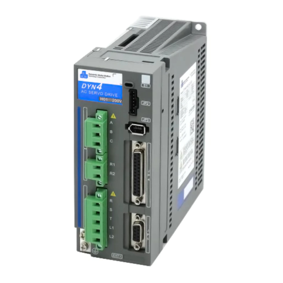
Page 9: Connection And Wiring
[ 8 ] [ 5 ] Protective earth / chassis ground EXT1 Extended interface connector [ 9 ] [ 6 ] [ 10 ] [ 11 ] DMM Technology Corp. REV. ZM7-A10A DYN4 AC Servo Drive Instruction Manual... -
Page 10: Connector Terminal And Signal Specification
Connector Type: Terminal Block Pin.2 Main circuit S Drive Header: (Phoenix) GMSTB 2.5/5-GF-7.62 Pin.3 Main circuit Plug Connector: (Phoenix) GMSTB 2.5/5-STF-7.62 Pin.4 Logic circuit L1 Pin.5 Logic circuit L2 DMM Technology Corp. REV. ZM7-A10A DYN4 AC Servo Drive Instruction Manual... -
Page 11: Jp4 Main I/O Terminal Details
- Active Low, servo drive runs to absolute zero when input LOW. Pin No. Symbol Details Interface Circuit - Servo hold input (Positive Direction) SHOLD - Servo drive ignores command input Input - Active High DMM Technology Corp. REV. ZM7-A10A DYN4 AC Servo Drive Instruction Manual... - Page 12 PUL+, A+, CW+ pulse reference Input Pin No. Symbol Details Interface Circuit - Internal signal ground Pin No. Symbol Details Interface Circuit AIN+ - Analog reference input POSITIVE Input DMM Technology Corp. REV. ZM7-A10A DYN4 AC Servo Drive Instruction Manual...
- Page 13 - Refer to section 3.3.2 for timing details Pin No. Symbol Details Interface Circuit - Absolute encoder position monitor output MO_ABS Output - Refer to section 4.6 for details DMM Technology Corp. REV. ZM7-A10A DYN4 AC Servo Drive Instruction Manual...
- Page 14 Symbol Details Interface Circuit - Servo drive internal +5VDC output +5VOUT Output - Max current draw: 50mA Pin No. Symbol Details Interface Circuit AIN- - Analog reference input NEGATIVE DMM Technology Corp. REV. ZM7-A10A DYN4 AC Servo Drive Instruction Manual...
-
Page 15: Jp4 Interface Circuit Examples
Circuit Example (Source Circuit) Notes Open Collector - PNP Transistor +14VDC / +24VDC 3kΩ 4,16 Example logic using +24VDC power supply: Power Supply PNP Transistor Voltage Level Signal +24VDC High DMM Technology Corp. REV. ZM7-A10A DYN4 AC Servo Drive Instruction Manual... - Page 16 - Recommended +24VDC or +5VDC [JP4-7] SRDY [JP4-18] ALM Circuit Example Notes Collector +5VDC 1kΩ 5,6,7,18 COM 5 Photocoupler +5VDC 1kΩ 5,6,7,18 COM 5 Relay 5~24VDC 5,6,7,18 COM 5 DMM Technology Corp. REV. ZM7-A10A DYN4 AC Servo Drive Instruction Manual...
- Page 17 █ Position Reference Pulse Input Circuit Interface Type Applicable Signals Specification - Voltage: +5VDC ± %10 [JP4-10] DIR- (Contact DMM if higher level such as 12/24VDC is required) [JP4-11] PUL+ [JP4-22] DIR+ - Max pulse frequency: 500kHz [JP4-23] PUL- - Minimum pulse width: 800us...
- Page 18 Potentiometer etc. AIN- █ Analog Output Circuit Interface Type Applicable Signals Specification - 0~3.3VDC output [JP4-8] MO_POS [JP4-20] MO_ABS - Max 0.33mA [JP4-21] MO_IC Circuit Example Notes 8,20,21 1,9,12 DMM Technology Corp. REV. ZM7-A10A DYN4 AC Servo Drive Instruction Manual...
-
Page 19: Jp4 Consolidated Interface Circuit
ABS_H 3kΩ SHOLD 3kΩ DIN4 3kΩ 270Ω PUL+, A+, CW+ PUL-, A-, CW- 270Ω DIR+, B+, CCW+ DIR-, B-, CCW- AIN+ Cable Shield AIN- JP4 Shell Twisted Pair Wires DMM Technology Corp. REV. ZM7-A10A DYN4 AC Servo Drive Instruction Manual... -
Page 20: Jp5 Encoder Output Terminal Details
Connection Circuit Line Drive/Receiver DYN4 Servo Drive JP5 Host Device AM26C31 AM26C32 or equivalent Use twisted pair shielded wires for each phase to minimize transmission noise. Open Collector Index Pulse DMM Technology Corp. REV. ZM7-A10A DYN4 AC Servo Drive Instruction Manual... -
Page 21: Main Circuit Wiring
Component Part DYN4-L01 DYN4-H01 DYN4-T01 MCCB Molded case circuit breaker Main Noise Filter FN355-6-05 FN355-10-05 FN355-20-03 AC Line Reactor (optional) Magnetic contactor Logic Fuse Logic Noise Filter 1A Schaffner FN2030-1-06 DMM Technology Corp. REV. ZM7-A10A DYN4 AC Servo Drive Instruction Manual... - Page 22 Component Part DYN4-L01 DYN4-H01 DYN4-T01 MCCB Molded case circuit breaker Main Noise Filter FN2030-6-06 FN2030-10-06 FN2030-16-06 AC Line Reactor (optional) Magnetic contactor Logic Fuse Logic Noise Filter 1A Schaffner FN2030-1-06 DMM Technology Corp. REV. ZM7-A10A DYN4 AC Servo Drive Instruction Manual...
- Page 23 L2 power conenction from one drive Power to another. Main Circuit Power 5. A terminal block can be used in Supply place of a relay terminal. Control Logic Power Supply Encoder DMM Technology Corp. REV. ZM7-A10A DYN4 AC Servo Drive Instruction Manual...
- Page 24 From From AC Power AC Power DYN4 Servo Drive DYN4 Servo Drive Main Circuit Power Main Circuit Power Supply Supply Control Logic Control Logic Power Supply Power Supply DMM Technology Corp. REV. ZM7-A10A DYN4 AC Servo Drive Instruction Manual...
- Page 25 It is much more efficient than conventional servo drives when handling servo motor regenerative energy. Generally, external regenerative resistors are not needed. If the servo drive often throws “Over Voltage“ alarm, contact DMM representative for regenerative energy sizing procedures. Resistors available from DMM:...
-
Page 26: Holding Brake Circuit Wiring
● Holding brake inertia will affect servo motor performance. Servo motors with holding brake option will have lower load inertia ratio capacity and angular acceleration. ● Holding brake is servo motor frame size-specific. Contact DMM representative for full specifica- tions. -
Page 27: Start - Up
Do not use daisy chain connection between each servo drive as it may cause noise and interference. Connect power source earth to one terminal and motor frame ground to other terminal. DMM Technology Corp. REV. ZM7-A10A DYN4 AC Servo Drive Instruction Manual... -
Page 28: Power Up Timing Chart
The residual voltage may cause the servo motor to rotate for a short period even after immediate power off. Consider this effect for emergency situations and take safety precaution to prevent damage to person- nel, equipment or machine. DMM Technology Corp. REV. ZM7-A10A DYN4 AC Servo Drive Instruction Manual... - Page 29 By factory default, the Enable logic is Active High. Servo drive is Enabled when powered up, without any input. Enable logic can be toggled in the DMMDRV program to Active Low if desired: DMM Technology Corp. REV. ZM7-A10A DYN4 AC Servo Drive Instruction Manual...
- Page 30 Motor Energy not energized Timing 4 - Servo Main Power OFF t1 = ≤100ms Servo Power t2 = ≤500ms brake disengaged brake engaged energized Motor Energy not energized DMM Technology Corp. REV. ZM7-A10A DYN4 AC Servo Drive Instruction Manual...
-
Page 31: Software Communication
Processor: Pentium 1 GHz or higher RAM: 512 MB or more Framework: .NET Framework 4 or higher Minimum disk space: 60MB *See User Manual DSFEN for complete set up instructions: DMM Technology Corp. REV. ZM7-A10A DYN4 AC Servo Drive Instruction Manual... - Page 32 2 ) Select the Servo mode 3 ) Click Save All to save the parameters to the servo drive 4 ) Refer to the next section (Section 4) for individual operation mode specifications DMM Technology Corp. REV. ZM7-A10A DYN4 AC Servo Drive Instruction Manual...
-
Page 33: Operation
4 Operation Position Servo Mode █ Pulse Specifications Voltage: +5VDC ± %10 (Contact DMM if higher level such as 12/24VDC is required) Max pulse frequency: 500kHz Minimum pulse width: 0.8μs ♦ Pulse + Direction t1, t4 ≥ 0.8μs t2, t3 ≤ 1.0μs t5, t6 ≥... - Page 34 A/B phase quadrature with 90° phase differential Forward Reference Reverse Reference JP4-11 JP4-11 JP4-22 JP4-22 A Leads B B Leads A ♦ CW + CCW Forward Reference Reverse Reference JP4-11 JP4-11 CCW+ CCW+ JP4-22 JP4-22 DMM Technology Corp. REV. ZM7-A10A DYN4 AC Servo Drive Instruction Manual...
- Page 35 DIR+, B+, CCW+ DIR-, B-, CCW- 1,9,12 ♦ Open Collector Output - External Power Supply 270Ω PUL+, A+, CW+ PUL-, A-, CW- 270Ω DIR+, B+, CCW+ DIR-, B-, CCW- DMM Technology Corp. REV. ZM7-A10A DYN4 AC Servo Drive Instruction Manual...
- Page 36 ~2 seconds. The servo position error is cleared when the drive is disabled using the ENA input and does not accumu- late when the drive is disabled. DMM Technology Corp. REV. ZM7-A10A DYN4 AC Servo Drive Instruction Manual...
-
Page 37: Speed Servo Mode
Voltage Speed Direction Direction +10V 6,000rpm 3,000rpm 3,000rpm 1,800rpm Reference Voltage -10V +10V Motor Speed █ Analog Input Specification See APPENDIX C for analog input scaling and deadzone settings. DMM Technology Corp. REV. ZM7-A10A DYN4 AC Servo Drive Instruction Manual... - Page 38 TrqCons can be increased up to 127 to ensure stability and fast dynamic following. The Torque Filter Constant parameter should only be used in speed and torque servo mode. Leave this parameter at “127” in position servo mode. DMM Technology Corp. REV. ZM7-A10A DYN4 AC Servo Drive Instruction Manual...
-
Page 39: Torque Servo Mode
Voltage Current Direction Direction +10V 20.0A 10.0A 10.0A 6.0A Reference Voltage -10V +10V Current Output █ Analog Input Specification See APPENDIX C for analog input scaling and deadzone settings. DMM Technology Corp. REV. ZM7-A10A DYN4 AC Servo Drive Instruction Manual... -
Page 40: Rs232 Command Input Mode
♦ Forward Reference = CW as viewed from motor shaft side CW Forward Reference CCW Reverse Reference JP5-6 JP5-6 JP5-7 JP5-7 A Leads B 90° B Leads A 90° DMM Technology Corp. REV. ZM7-A10A DYN4 AC Servo Drive Instruction Manual... -
Page 41: Servo Drive Monitor Outputs
65,536 32,768 65,536 Absolute Position 3.3V Reverse 1.65V Rotation 32,768 65,536 32,768 65,536 Absolute Position Time per motor rotation [s] = 32*t Servo motor rotation speed [rpm] = 1,920/t DMM Technology Corp. REV. ZM7-A10A DYN4 AC Servo Drive Instruction Manual... - Page 42 [ 0V : 3.3V ]. 3.3V JP4-8 Servo Motor Position Error Analog Output 1.65V 1,500pulse (8.24°) 3.3V 1.65V -1,500pulse (-8.24°) -1,500 1,500 Servo Motor Position Error [pulse] DMM Technology Corp. REV. ZM7-A10A DYN4 AC Servo Drive Instruction Manual...
-
Page 43: Parameters And Tuning
SpeedGain is used. If a very RS232 quick response servo with small load is desirable, a bigger value or even the max value 127 should be used to ensure the dynamic stability. DMM Technology Corp. REV. ZM7-A10A DYN4 AC Servo Drive Instruction Manual... - Page 44 Pulse output per rev = LINE_NUM * 4 Torque RS232 If LINE_NUM = 2,000 then 8,000 pulses will be output per servo motor revolution. Pulse output active for all servo modes. DMM Technology Corp. REV. ZM7-A10A DYN4 AC Servo Drive Instruction Manual...
-
Page 45: Servo Drive Gain Tuning
Speed Gain until decrease Speed Gain decrease Speed Gain overshooting suppressed If still unstable If still unstable If still unstable Decrease Decrease Integration Gain Decrease Integration Gain Torque Filter Constant DMM Technology Corp. REV. ZM7-A10A DYN4 AC Servo Drive Instruction Manual... - Page 46 MDRV program includes the Auto Tuning module. Follow the instructions in the module to allow the program and servo drive to automatically tune the Main Gain, Speed Gain, Integra- tion Gain and Torque Filter Constant Parameters. DMM Technology Corp. REV. ZM7-A10A DYN4 AC Servo Drive Instruction Manual...
-
Page 47: Maintenance
JP3 port of the servo drive. Over Current above rated and protection levels. - Check for any mechanical irregularities that might be preventing the motors to move freely. DMM Technology Corp. REV. ZM7-A10A DYN4 AC Servo Drive Instruction Manual... -
Page 48: Servo Drive Maintenance
Servo Drive Maintenance Do not perform maintenance on the servo drive unless instructed to do so by DMM. The servo drive cover or chassis should never be removed as high voltage components can cause electric short, shock or other damage upon contact. -
Page 49: Rs232 Communication Protocol
EEPROM busy in writing parameters all the time and also shorten it’s lifetime. The guaranteed parameter writing cycle for EEPROM is 1 million times. Once a group of parameters and configuration are set, use it until next necessary change. DMM Technology Corp. REV. ZM7-A10A DYN4 AC Servo Drive Instruction Manual... -
Page 50: Interface And Format
8-bit Full Duplex Asynchronous (UART) Voltage +5V (TTL/CMOS) Fast Mode is custom option - contact DMM for details. All specifi- cations in this manual are referenced in standard mode. DMM Technology Corp. REV. ZM7-A10A DYN4 AC Servo Drive Instruction Manual... - Page 51 The DYN servo drive will send each byte immediately after another, so at 38400 baud, each byte will take approximately 260us to transmit - host controller should read or sample at this rate or faster when receiving data. DMM Technology Corp. REV. ZM7-A10A DYN4 AC Servo Drive Instruction Manual...
-
Page 52: Packet Definition
The communicating servo drive must be set to the same ID number to accept and execute data. The drive ID can only be set if the RS485/232 Net check box is not checked (in the DMMDRV software). DMM Technology Corp. REV. ZM7-A10A... - Page 53 See section 7.5 Example 11 ; See section 7.4 Read_Pos_OnRange 0x1e 1(dummy) See section 7.5 Example 11 Read_GearNumber 0x1f 1(dummy) See section 7.5 Example 11 ; See section 7.4 DMM Technology Corp. REV. ZM7-A10A DYN4 AC Servo Drive Instruction Manual...
- Page 54 Minimum packet length is 4. There is at least one data byte, for some function code that does not require data, this data byte is meaningless, or called dummy byte which can be set to any value [0~127] and does not affect the overall function of that packet. DMM Technology Corp. REV. ZM7-A10A DYN4 AC Servo Drive Instruction Manual...
- Page 55 S = B3 + B2 + B1 = 0x144 = 324 B0 = 0x80 + Mod(S , 128) = 0x80 + Mod(324, 128) = 0x80 + 0x44 B0 = c4 DMM Technology Corp. REV. ZM7-A10A DYN4 AC Servo Drive Instruction Manual...
-
Page 56: Drive Configuration And Status Register
The default Config = x0000000, RS232 communication mode, absolute position sensor works as relative mode, position servo, servo enabled. If the bit 5 of Config register is set to be 1, Drive will let motor shaft free (servo disabled). DMM Technology Corp. REV. ZM7-A10A DYN4 AC Servo Drive Instruction Manual... -
Page 57: Common Function Details
Constant Speed Travel Time = 0.154 s Total S-Curve Time = 0.362 s 2500 0.104s 0.258s 0.362s 1985rpm 2000 1500 1000 0.05 0.10 0.15 0.20 0.25 0.30 0.35 0.40 Time (s) DMM Technology Corp. REV. ZM7-A10A DYN4 AC Servo Drive Instruction Manual... - Page 58 The motion is executed as soon as the Sin_Wave function is received. Note that Sin_Wave and Square_ Wave shares the same SS_Frequency data value. The sine waveform is generated internally within the DYN servo drive. DMM Technology Corp. REV. ZM7-A10A DYN4 AC Servo Drive Instruction Manual...
-
Page 59: Dynamic Target Position Update ( Dtpu )
Robotic movements can be controlled and commanded in real-time, significantly simplifying kinematic motion planning requirements on the controller. Machine-level trajectory planning can almost be eliminated. DMM Technology Corp. REV. ZM7-A10A DYN4 AC Servo Drive Instruction Manual... - Page 60 : Current positioning reached, axis commanded to retract Time With DTPU : Safety warning/hazard detected, axis commanded to retract : Axis immeidately retracts to safe position Time DMM Technology Corp. REV. ZM7-A10A DYN4 AC Servo Drive Instruction Manual...
-
Page 61: Packet Structure Examples
1 0 0 11 0 0 1 1 b6 b5 b4 b3 b2 b1 b0 1 x x x x x x x Packet Length = 4 Drive status data Function = 0x19 DMM Technology Corp. REV. ZM7-A10A DYN4 AC Servo Drive Instruction Manual... -
Page 62: Application Examples
S = B4 + B3 + B2 + B1 = 0x03 + 0xa3 + 0x80 + 0xf8 = 0x21e B0 = 0x80 + Mod(S , 128) = 0x80 + 0x1e = 0x9e DMM Technology Corp. REV. ZM7-A10A DYN4 AC Servo Drive Instruction Manual... - Page 63 B1 = 0x80 + 0x44 = 0xc4 S = B3 + B2 + B1 = 0x02 + 0x8a + 0xc4 = 0x150 B0 = 0x80 + Mod(S , 128) = 0x80 + 0x50 = 0xd0 DMM Technology Corp. REV. ZM7-A10A DYN4 AC Servo Drive Instruction Manual...
- Page 64 Drives status register to check whether b5 = 0 or not, b5 = 0 means the coordinated motion be finished. Two equal half arcs must be made to make a circle. DMM Technology Corp. REV. ZM7-A10A DYN4 AC Servo Drive Instruction Manual...
- Page 65 Read servo drive Main Gain parameter Method: Call ReadMainGain() subroutine function DYN drive Main Gain stored in MainGain_Read variable Use the same subroutine format for all Parameter Read functions 0x18~ 0x1f. DMM Technology Corp. REV. ZM7-A10A DYN4 AC Servo Drive Instruction Manual...
-
Page 66: Rs485 Network
ID is correct and relay to next drive if ID does not match. Data flow on the serial RS485 net is very fast and efficient. Every drive has a RS485NET node which contains a RS485 buffer such as LTC491. DMM Technology Corp. REV. ZM7-A10A DYN4 AC Servo Drive Instruction Manual... -
Page 67: A Appendix : C++ Code For Serial Communication Protocol
= c>>5; cif = cif&0x03; Read_Package_Length = 4 + cif; c = 0; if(Read_Num==Read_Package_Length) Get_Function(); Read_Num = 0; Read_Package_Length = 0; C++ Code for Serial Communication - Page 1 DMM Technology Corp. REV. ZM7-A10A DYN4 AC Servo Drive Instruction Manual... - Page 68 OneChar = One_Package[i]; OneChar &= 0x7f; Lcmd = Lcmd<<7; Lcmd += OneChar; return(Lcmd); /* Lcmd : -2^27 ~ 2^27 - 1 */ C++ Code for Serial Communication - Page 2 DMM Technology Corp. REV. ZM7-A10A DYN4 AC Servo Drive Instruction Manual...
- Page 69 TempLong == 0x00000000) || ( TempLong == 0xffffffff)) {//One byte data B[2] = B[3]; Package_Length = 4; B[1] += (Package_Length-4)*32 + Function_Code; Make_CRC_Send(Package_Length,B); C++ Code for Serial Communication - Page 3 DMM Technology Corp. REV. ZM7-A10A DYN4 AC Servo Drive Instruction Manual...
- Page 70 MotorTorqueCurrentReady_Flag = 0xff; While(MotorTorqueCurrentReady_Flag != 0x00) ReadPackage(); //MotorTorqueCurrentReady_Flag is cleared inside ReadPackage() or inside //Get_Function() exactly after the MotorTorqueCurrent is updated. C++ Code for Serial Communication - Page 4 DMM Technology Corp. REV. ZM7-A10A DYN4 AC Servo Drive Instruction Manual...
- Page 71 Global_Func = (char)Go_Absolute_Pos; Send_Package(Axis_Num,Pos32); void ReadMainGain(char MotorID) char Axis_Num = MotorID; Global_Func = (char)Read_MainGain; Send_Package(Axis_Num, Is_MainGain); MainGainRead_Flag = 0xff; while(MainGainRead_Flag != 0x00) ReadPackage(); C++ Code for Serial Communication - Page 5 DMM Technology Corp. REV. ZM7-A10A DYN4 AC Servo Drive Instruction Manual...
- Page 72 /* (6) Reading the main gain of 8th axis servo drive using subroutine function*/ ReadMainGain(8); //Main Gain stored in MainGain_Read variable C++ Code for Serial Communication - Page 6 DMM Technology Corp. REV. ZM7-A10A DYN4 AC Servo Drive Instruction Manual...
- Page 73 Data is processed as first-in-first-out (FIFO) queue and starts at the index of InBfBtmPointer. InBfBtmPointer is incremented each time a byte is processed until InBfBtmPointer=InBfTopPointer, meaning all packet bytes have been processed. C++ Code for Serial Communication - Page 7 DMM Technology Corp. REV. ZM7-A10A DYN4 AC Servo Drive Instruction Manual...
-
Page 74: Modbus Rtu (Rs485) Communication
The DYN4-□□□B2-00 servo drive models are compatible with Modbus RTU communication over 2-Wire RS485. Please refer to the following manual for Modbus communication specification: Document Number DYNMB1-BL1645 DYN AC Servo Drive Modbus RTU Specification DMM Technology Corp. REV. ZM7-A10A DYN4 AC Servo Drive Instruction Manual... -
Page 75: Can Communication
5-bit Function Code b5~b10 = Drive ID 0~64 0 = Broadcast Function Code: CAN Command 5-bit Function Code Data Length (Bytes) Set_Origin 0x00 Go_Absolute_Pos_PTP 0x01 Make_LinearLine 0x02 Go_Relative_Pos_PTP 0x03 DMM Technology Corp. REV. ZM7-A10A DYN4 AC Servo Drive Instruction Manual... -
Page 76: Appendix
Ø5.2 DYN4 AC Servo Drive AC Servo Drive Dynamic Motor Motion Technology Corporation DYN4 Series Name Plate Custom Model Name Plate EXT1 ■ Cable Spacing Leave at least 60mm space in front of the servo drive for cable spacing. Ensure the cables are not pulling on the connectors or pins. -
Page 77: Appendix B - Application Note# Ap15-48 Dyn4 Servo Drive - Ac Power Supply Guidelines
120VAC at the primary voltage and 240VAC at the secondary voltage, connect the 240VAC to both L1/L2 and R/S/T. Do not connect 120VAC into L1/L2 and 240VAC into R/S/T. DMM Technology Corp. REV. ZM7-A10A DYN4 AC Servo Drive Instruction Manual... -
Page 78: Appendix C - Analog Input Fine Adjustments
By applying +5V to JP4 Pin22 and 0V (Gnd) to Pin10, the rotation direction is reversed to CCW. This direction change can be made on-the-fly during normal operation. DMM Technology Corp. REV. ZM7-A10A DYN4 AC Servo Drive Instruction Manual... -
Page 79: Warranty And Liability
Within the warranty period, DMM Technology Corp. will replace or repair any defective product free of charge given that DMM Technology Corp. is responsible for the cause of the defect. This warranty does not cover cases involving the following conditions: ●... -
Page 80: Product And Manual Disclaimer
█ Disclaimer DMM Technology Corp. constantly strive to improve its product performance and reliability. The contents of this manual outlines the latest features and specifications of the DYN4 AC Servo Drive and may be changed at any time to reflect corrections, improvements or changes to the product or information in this manual. -
Page 81: Document Revisions
Various design and layout improvements - Added DYN232M Section March 2015 A1.5 - Formatting improvements - Revised command pulse specifications January 2015 A1.2 - Added JP3 encoder feedback pinout DMM Technology Corp. REV. ZM7-A10A DYN4 AC Servo Drive Instruction Manual... - Page 82 A, DYN4 - B, DYN4 - MANUAL CODE: DYN4MS-ZM7-A10A REVISION: A1.0A Electronic Version Copyright © 2018 DMM Technology Corp. Published In Canada DMM TECHNOLOGY CORP. 120 - 21320 Gordon Way Richmond, British Columbia V6W1J8 Canada PHONE: +1 (604)-370-4168 FAX: +1 (604) 285-1989 WEB: http://www.dmm-tech.com...
Need help?
Do you have a question about the DYN4 Series and is the answer not in the manual?
Questions and answers