Table of Contents
Advertisement
Advertisement
Table of Contents

Related Manuals for Zline RA-WM-24


Summary of Contents for Zline RA-WM-24
- Page 1 anges Installation Guide and Users Manual...
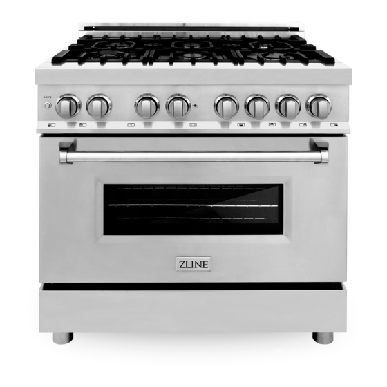
- Page 3 Never sacrifice power for performance with a ZLINE range. Enjoy the luxury of cast iron grills, triple layer insulated glass paneling, and a high-gloss black porcelain cooktop. Utilizing items engineered and crafted in Italy, this range is on the top...
-
Page 4: Table Of Contents
CONTENTS Installation Guide IMPORTANT SAFETY INSTRUCTIONS WARRANTY AND SERVICE PRODUCT DIMENSIONS BEFORE INSTALLATION INSTALLING THE LEGS INSTALLING THE CHAINS INSTALLATION REQUIREMENTS POWER RATING & ELECTRICAL CONNECTION WIRING SCHEMATICS GAS CONNECTION GAS CONVERSION PROCEDURE INSTALLATION CHECKLIST FINAL PREPARATION... - Page 5 CONTENTS Users Manual ROOM VENTILATION COOKTOP COOKING USING THE OVEN MAINTAINING YOUR RANGE CHANGING DOORS TROUBLESHOOTING...
- Page 6 ZLINE product. This manual will help you learn to use the product in the safest, most efficient manner, and care for it so that it may give you the highest satisfaction for years to come.
-
Page 7: Important Safety Instructions
Important Safety Instructions An air curtain or other overhead range/cooktop hood which operates by blowing downward airflow onto the range, shall not be WARNING used/installed in conjunction with this gas range. The manufacturer will not be responsible for any damage to property or to persons caused by incorrect installation, improper use of the appliance, or failure to heed the warnings listed. - Page 8 Important Safety Instructions Please read and follow these important instructions for the safety of your home and the people living in it. If the information in this manual is not followed exactly, a fire or explo- sion may result causing property damage, personal injury, or death. WARNING Do not store or use gasoline or any other flammable substances in the vicinity of this or any other appliance.
-
Page 9: Warranty And Service
Service on all products shall be carried out by industry professionals only. For warranty service, please call customer service. Replacement Parts Only authorized replacement parts may be used in performing service on this appliance. Call 1-614-777-5004. Replacement parts are available from ZLINE. -
Page 10: Product Dimensions
Product Dimensions 2 “ 2"5/16(59) “ 7"13/16(198.5) 13 / 27 “ 27"7/16(695) 2 “ 2"3/4(70) 3/16"(5) “ 1 “ 1"1/4(33) 21 “ 2 “ 2 “ 21"1/8(537) 2"9/16(65) 2"3/16(54.5) “A” will change with size of range (24”, 30”, 36”, 48”, 60”) - Page 11 Product Dimensions External Dimensions: 24” Model: 24”W x 27.4”D x 36”H 30” Model: 30”W x 27.4”D x 36”H 36” Model: 36”W x 27.4”D x 36”H 48” Model: 48”W x 27.4”D x 36”H 60” Model: 60”W x 27.4”D x 36”H Internal Dimensions 24”...
-
Page 12: Before Installation
Before Installation This appliance shall only be installed by an authorized professional. The appliance shall be installed in accordance with the standards of the country where it will be installed. The installation of this appliance must conform to local codes and ordinances. In the absence of local codes installation must conform to American National Standards, National fuel Gas code ANSI Z223.1-Latest edition/ NFPA 54 or B 149.1. - Page 13 Before Installation Room Ventilation An exhaust fan may be used with the appliance; in each case it shall be installed in conformity with the appropriate national and local standards. Exhaust hood operation may affect other vented appliances; in each case it shall be installed in conformity with the appropriate national and local standards.
-
Page 14: Installing The Legs
Installing the Legs The ranges must be used with the legs properly installed. Height-adjustable legs are shipped with the range in a foam container above the range. Installing the Legs 1. Before installing the legs, position the appliance near its final location, as the legs are not suitable for moving the appliance over long distances. -
Page 15: Installing The Chains
Installing Chains Installing the chains The chains shipped with the range must be properly secured to the rear wall, as shown in the picture on the following page. The height of the bracket from the floor must be determined after the range legs have been adjusted to the desired height and after the range has been leveled. -
Page 16: Installation Requirements
Installation Requirements A properly grounded and horizontally-mounted electrical receptacle type NEMA 14- 50R should be installed no higher than 3” above the floor, no less than 2” and not more than 8” from the left side (facing product); refer to electrical connection section. An agency-approved, properly-sized manual shut-off valve should be installed no higher than 3”... - Page 17 Installation Requirements Cooking Range Front View Side View 30” to 36” 13” to bottom of 30” ventilation hood 27 ¹/ ” 6” opening width 36-38” 3.23” to cooking 3.23” surface location of gas and electrical 5 ³/ ” extends on floor 8”...
-
Page 18: Power Rating & Electrical Connection
Power Rating & Electrical Connection The appliance shall be connected to a single phase electric line rated at 120/208Vac or 120/240Vac and 60Hz frequency. Electric Power Rating 24” - 36” model 120/240Vac: 20A max 48” model 120/240Vac: 30A max 60” model 120/240 Vac: 40A max Heating Element Power Rating Main oven... - Page 19 Power Rating & Electrical Connection Four-Wire Connection Receptacle NEMA 14-50R L2 (red) L2 (red) N (white) N (white) cable from power supply G (green) G (green) L1 (black) L1 (black) Electrical Grounding Our oven is equipped with a four-prong plug for your protection against shock hazard and should be plugged directly into a properly grounded receptacle.
-
Page 20: Wiring Schematics
Wiring Schematics Model: RA24 Model: RA30... - Page 21 Wiring Schematics Model: RA36 Model: RA48...
- Page 22 Wiring Schematics Model: RA60...
-
Page 23: Gas Connection
GAS CONNECTION All gas connections must comply with national and local codes. The gas supply line (service) must be the same size or greater than the inlet line of the appliance. This range uses a ½˝ NPT inlet. Use appropriate sealant on all pipe joints that are resistant to gas. - Page 24 Gas Connection Manual Shut-Off Valve This valve is not shipped with the appliance and must be provided by the installer. The manual shut-off valve must be installed in the gas service line between the gas hook-up on the wall and the appliance inlet, in position where it can be reached quickly in the event of an emergency.
- Page 25 Gas Connection Pressure Regulator Since service pressure may fluctuate with local demand, every gas cooking appliance must be equipped with a pressure regulator on the incoming service line for safe and efficient operation. Pressure Regulator The pressure regulator shipped with the appliance has two female threads 34”NPT. The regulator shall be installed properly in order to be accessible when the appliance is installed in its final position.
- Page 26 Gas Connection The gas conversion procedure for this range includes: 1. Pressure Regulator 2. Surface Burners 3. Flame Adjustment The conversion is not finished if all steps are not completed. Before performing the gas conversion, locate the package containing the replacement nozzles, which has a number indicating its flow diameter printed on the body.
- Page 27 Gas Connection Propane Conversion Video...
-
Page 28: Gas Conversion Procedure
Gas Conversion Procedure Step 1: Pressure Regulator The pressure regulator supplied with the appliance is a convertible type pressure regulator for use with Natural Gas at a nominal outlet pressure of 4˝ w.c. or LP gas at a nominal outlet pressure of 1 1” w.c. and it is pre-assembled from the factory to operate with one of these gas pressure as indicated in the labels affixed on the appliance, package, and instruction booklet. - Page 29 Gas Conversion Procedure Step 2: Surface Burners To replace the nozzles of the surface burners, lift up the burners and unscrew the nozzles shipped with the range using a 7 mm (socket wrench). Replace nozzles using the conversion set supplied with the range. Each nozzle has a number indicating its flow diameter printed on the body.
- Page 30 Flame Adjustment 1. Light one burner at a time and set it to the MINIMUM position (small flame). 2. Remove the knob. 3. The range is equipped with a safety valve. Using a small-size flathead screwdriver, locate the choke screw (see diagram below) and turn to the right or left until the burner flame is adjusted to desired minimum.
-
Page 31: Installation Checklist
Installation Checklist 1. Is the range mounted on its legs? 2. Is the back guard securely connected? 3. Have the chains been properly installed? 4. Does the clearance from the side cabinets comply with the manufacturers’ direction? 5. Is the electricity properly grounded? 6. -
Page 32: Users Manual
Users Manual... -
Page 33: Room Ventilation
Room Ventilation The use of a gas cooking appliance generates heat and humidity in the room where it is installed. Proper ventilation in the room is needed. Make sure the kitchen is equipped with a range hood of appropriate power (400 CFM minimum). Activate the exhaust fan/range hood when possible. - Page 34 COOKTOP COOKING This product is intended for the cooking of food and must not be used for other purposes. Unstable or deformed pans should not be placed on the burners or hot plates in order to avoid accidents caused by spill over. Particular care should be taken when cooking with oil or fat.
- Page 35 COOKTOP COOKING Surface Burner Operation - Electric Ignition To activate the electric ignition, simply turn the control knob counter-clockwise to maximum power, then press the knob in to start the flow of gas and the ignition spark. The spark will be released at the metal tip of the white ceramic pin located on the side of the burner.
- Page 36 COOKTOP COOKING Be sure to set all worktop/oven/broiler burner controls to the OFF position after each use of the appliance. Maximum Flame Height Minimum Flame Height Maximum temperature setting/recommended control knob position for burner ignition. The regulating knobs should be turned in anti-clockwise direction until the small flame symbol, vice- versa for the larger flame symbol.
-
Page 37: Using The Oven
Using the Oven Oven Function Selectors - RA/RAB/RAS models The temperature dial must be set to the preferred temperature and the baking dial must be set to the preferred cooking function. Symbols: Oven Functions Selector Symbols: Oven Functions Selector High Conv. - Page 38 Using the Oven Using Pans Correctly 1. Always ensure that the bottom and handles of pans do not protrude over the worktop. 2. When cooking with flammable fat, such as oil, do not leave the range unattended. 3. Use pots of the appropriate size on each burner following the indication of the diagram below.
- Page 39 Using the Oven Placement of Oven Racks Continued 5. DO NOT TOUCH HEATING ELEMENTS OR INTERIOR SURFACE OF OVEN. Heating elements may be hot even though they are dark in color. Interior surfaces of an oven become hot enough to cause burns. During and after use, do not touch, or let clothing or other flammable materials come into contact with the heating elements or interior surfaces of the oven until they have had sufficient time to cool.
-
Page 40: Maintaining Your Range
Using the Oven High Bake/Preheat: This setting is the optimum setting for roasting and baking, suggested use if for baking at temperatures 375-525 degrees. High Bake will use both the bottom element and the center ring of the top element for even cooking and optimal oven temperatures. - Page 41 Maintaining Your Range Cleaning Your Range During cleaning operation, never move the appliance from its original installation position. Never use abrasive cleaners! Scratches on the WARNING stainless steel surfaces are permanent. Do NOT clean the range when hot! Cleaning after Installation: Use a stainless steel cleaning product or wipe to eliminate the glue residues of the protection film after removal.
-
Page 42: Changing Doors
Changing Doors 1. Install the pins into slots on each hinge (pins not included.) 2. Carefully lift the door out of the range. 3. Uninstall the kick plate by unscrewing the four screws in the corners of the kick plate. There are two at the top and two at the bottom on each side. Have another helper tilt the range to unscrew the bottom screws. -
Page 43: Troubleshooting
Troubleshooting Range Problem Possible Cause and/or Remedy Range does not function Range is not connected to electrical power. Check power circuit breaker, wiring, and fuses. If all electrical components are properly installed, call customer support. Broil does not work Temperature control knob is rotated too far past broil position (500°F);... - Page 44 Kitchen and Bath Three Locations: 350 Parr Circle Reno, NV 89512 916 Delaware Avenue Marysville, OH 43040 427 Rowland Mill Road Bruceton, TN 38317 www.zlinekitchen.com 1-614-777-5004 1.0.0...