Table of Contents
Advertisement
Quick Links
Advertisement
Table of Contents

Subscribe to Our Youtube Channel
Related Manuals for CSI CSI-DSP85-C/P


Summary of Contents for CSI CSI-DSP85-C/P
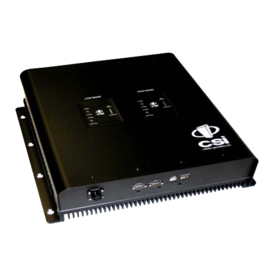
- Page 1 CSI-DSP85-C/P , CSI-DSP85I-C/ P & CSI-DSP85-201-C/P Installation Manual...
-
Page 2: Table Of Contents
Table Of Contents Product Registration Information ........4 Document Purpose/Intended Users ........4 Application ..............4 Safety Guidelines and Important Safety Information....4-5 Terms Used in This Manual ..........5 Product Introduction ............5 DSP Band Plan and Filter Naming Convention ..6-7 Functional Overview ..........8 LED Indicators ............8-9 Local Communications Interface Ports .....10 Pin-out Chart .............10 USB Interface .............10... -
Page 3: Product Registration Information
DISCLAIMER: All information and statements contained herein are accurate to the best of the knowledge of Cellular Specialties, Inc. (CSI), but Cellular Specialties makes no warranty with respect thereto, including without limitation any results that may be obtained from the products described herein or the infringement by such products of any proprietary rights of any persons. -
Page 4: Terms Used In This Manual
The following pages describe the Cellular and PCS band plans as well as the convention CSI uses to identify and store the files that make up the filter set. All DSP85-C/P and DSP85I-C/P repeaters are shipped with an active filter set that is programmed according to the ordering parties’... -
Page 5: Dsp Band Plan And Filter Naming Convention
Cellular Frequency Band Plan Uplink 846.5 (MHz) Downlink 891.5 (MHz) A’ B’ SMR 900 SM800 A” Public SMR 800 Safety iDEN UL 896-901 UL 794-806 UL 806-821 UL 821-824 UL 824-825 UL 825-835 UL 835-845 UL 845-846.5 UL 846.5-849 DL 764-776 DL 851-866 DL 866-869 DL 869-870... - Page 6 Note: Filter file names will be from six to twelve characters long. Each character position in the filter file name is used to define the characteristics of the filter as shown above. All frequencies are shown in MHz - 7-...
-
Page 7: Functional Overview
Functional Overview The CSI-DSP85-C/Pand CSI-DSP85I-C/P repeaters incorporates the following features for convenient operation, access, protection, and control. • Network Configuration and Control using either a webpage style GUI through any standard browser or a menu driven user interface using the serial port. - Page 8 When boot is complete and no alarm conditions exist, none of the LED indicators will be illuminated. The CSI logo is illuminated when ever the repeater is powered. One or more bars on the LED bargraph may also be lit, depending on the strength of the signal being received from the donor site.
-
Page 9: Local Communications Interface Ports
Local Communication Interface Ports To allow monitoring and control, the repeater is equipped with four ports that provide external communication access (1 Ethernet CAT-5, 2 DB-9 serial, and 1 USB). The Ethernet, CAT-5 port is provided as a primary communications port to the PC. One serial interface provides commu- nications to local PC and the second to an external modem when provided. -
Page 10: System Set-Up Considerations
DONOR PORT If a CSI-DSP85-C/P or CSI-DSP85I-C/P is installed in an area with very strong desired and/or undesired signals, it is important to ensure that the overall signal levels are optimized to be within the best operating range of the repeater. - Page 11 SERVER PORT Server port attenuation may also be necessary, particularly where a powered DAS is present. The selection guidelines below apply to both server and donor ports. In order to properly measure uplink signal strength, a signal generator should be used. If a signal generator is not available, placing a test call while under the server antenna with the least path loss to the repeater should provide reasonable data.
-
Page 12: Mounting The Repeater
Wall Mounting the Digital Repeater The following diagram illustrates the best method for mounting the repeater to a wall in a typical installation. Note: for optimal cooling the unit should be mounted vertically on a wall with the antenna ports up. ITEM # PART # DESCRIPTION... -
Page 13: Optional Accessories
Optional Accessories A complete line of accessories is available from Cellular Specialties, Inc. Check with your CSI distributor for any additional items needed. Below are just a few examples suitable for most in-building needs. •Outside Donor Antenna •UPS PCS - model number: CSI-AY/1.85-1.99/10... -
Page 14: Function Block Diagram
Functional Block Diagram - 15 -... -
Page 15: Mechanical Specifications
Mechanical Specifications Parameter Specification Notes Repeater Size Height 4.69 in. Width 18.62 in. Depth 19.25 in. Box Weight 35.0 / 15.9 lbs/kg Box Thermal Management Convection cooled Large heatsink Surface Coating Powder Coat Color Satin Black AC Power Specifications Parameter Specification Notes AC Voltage... -
Page 16: Operating Power Parameters
In 0.5 dB steps Linear Output Power + 27dBm max Uplink and Downlink CELL +26dBm ** **AGC Set Point (CSI-DSP85-C/P & CSI-DSP85I-C/P) PCS +25dBm ** Linear Output Power + 30dBm max Uplink and Downlink CELL +29dBm ** **AGC Set Point... -
Page 17: Mechanical Drawing
Mechanical Drawing TO INSIDE ANTENNA TO OUTSIDE ANTENNA CELL CELL LOW BAND HIGH BAND ALA RM ALARM SIGNAL SIGNAL UL PWR UL PWR DL PWR DL PWR STRENGTH STRENGTH SHUT DWN SHUT DWN POWER ETHERNET COM 2 COM 1 -18 -... -
Page 18: Web Base Gui Session
Web based GUI Session Primary access to the repeater is gained using a LAN connection and a web browser program such as Firefox by Mozilla, or Internet Explorer from Microsoft. The repeater ships with the default IP address of 192.168.1.100, but it can be changed later if required. If connecting directly to the repeater from a laptop or PC with a crossover CAT-5E cable over a LAN the user types the IP address of the repeater into the browser address line to... - Page 19 Local Network: If the user selects Local Network from the System Status page, the following screen is displayed and from here network configuration can be modified as required. The default is set to Static. Check with your IT department for explanation and approval of the DHCP and DHCP Server options you plan to use before you select them.
- Page 20 RF Configuration: If the user would like to modify RF configuration, click on the words RF Configuration in the navigation box and the screen below is displayed. To change gain settings the user will select the Uplink only or Uplink and downlink radio buttons. The user then inputs the gain value desired.
- Page 21 The time required to complete this process will take just a few moments. Note: If the filter desired is not currently in the unit, additional filters along with instructions on how to load them, are available by contacting CSI. - 22 -...
- Page 22 Remote Network: If the repeater includes a modem kit, click on Remote Network in the navigation box and the screen below is displayed. Highlight the carrier on whose network the repeater and modem will be configured and click the Change Settings button. Refer to the documentation included with the modem kit for additional information on configuring the modem.
- Page 23 Should a software install or upgrade be needed it can be done from the Install & Upload screen shown below. As with the other screens it can be reached by clicking the words in the naviga- tion box. Contact CSI for updates and instructions. - 24 -...
- Page 24 Alarm Configuration: The Alarm Configuration page allows the user to specify what events will trigger an alarm. *NOTE: Letters, numbers & hyphens are the only acceptable nomenclature for the Location field and hyphens may not be used as the first or last character. Email Configuration: Email Configuration page allows the user to enter up to five Email addresses to which the repeater can send specified alarm messages when Email Alarm Notification and Remote Networking are enabled, and the repeater is equipped with...
- Page 25 Reboot: If a reboot of the repeater becomes necessary click on the Reboot option in the navigation box and the Reboot page is displayed. Note: a reboot will take 3-5 minutes to complete. Log Configuration: The Log Configuration page provides the user with the means to change three aspects of how log files are created and stored as shown below.
-
Page 26: Text Menu Interface (Local Access)
Text Menu Interface (Local Access) Local access to the repeater TMI, also known as the console interface, is made by connecting a serial cable (optional), as shown in Figure 1, from the serial connector of the laptop to either of the serial ports on the bottom end panel of the repeater. - Page 27 Select the Serial radio button and press OK as shown below. System Status Screen Single Band 7-22-09a Note: It may be necessary, in the System Properties section of the control panel; using Device Manager to determine what COM port your computer uses for the communications port. In this case it is COM 1.
- Page 28 TMI main menu will appear. Note: by default the Set Parameters option is disabled. To re-enable the user will press 1 and will be prompted for a username and pass- word. The default user name is csi and the password is csi1234. The actions displayed are self-explanatory.
- Page 29 Each “Set Parameter” selection, when chosen will be expanded to allow changing or setting of that parameter. For example from the Link Configuration menu on the previous page, selecting 1 - Adjust Gain will display the menu shown below. After selecting option 1, downlink, the current user gain is displayed and the option to change it is accomplished by typing the desired gain at the prompt.
-
Page 30: Telnet Session (Remote Access, Login Required)
All the other options operate in much the same way. Some of the options will offer the user additional selections and will be self-explanatory. Below is one example of these additional options, the one shown below is the result of selecting (3) Filter Programming. Note: Graceful session termination is important. - Page 31 Pressing the “OK” button will bring the user to the following screen, which will require the user to log in. In dual band units, each band is changed independently and requires an independent login. To make changes to the cellular band the default user name is “cellband”. The default user name for changing the PCS band is “pcsband”.
-
Page 32: Modem Interface (Remote Access With Login)
Telnet and serial sessions both provide access to the same Text Menu Interface. This manual has already discussed many of the options available, those as well as the options not covered are self explanatory, so they will not be repeated in the Modem Interface section. - Page 33 Right click on Local Area Connection - and select “Properties”. Scroll down and highlight “Internet Protocol (TCP/IP) and click on the “Properties” button. If you are set up to use DHCP, the window shown below will be displayed. Select “Use the following IP address:” and enter “192.168.1.2.” The subnet mask should automatically populate to “255.255.255.0.
- Page 34 Nothing else will need to be chosen or entered. Click “OK”, then “OK” again and retry connection. A crossover Ethernet cable (supplied) must be used for Web Interface access. As a reminder, you must verify the Ethernet port on your laptop is powered. If your laptop is on battery power, the Ethernet port may be inactive by default.
-
Page 35: Product Warranty
One Year Limited Warranty Seller warrants that its products are transferred rightfully and with good title; that its products are free from any lawful security interest or other lien or encumbrance unknown to Buyer; and that for a period of one year from the date of installation or fifteen months from the date of original shipment, which- ever period expires first, such products will be free from defects in material and workmanship which arise under proper and normal use and service. -
Page 36: Index
Warranty 36 Circuit Operational Description Web based GUI Session 19 Noise Figure 17 14, 19, 20, 21, 22, 23, 24, 25, 26 CPU 5 CSI 5 OIP3 17 Optional Accessories 14 OSC 9 D/L SIGNALSTRENGTH: 9 DAS 5 DHCP 5... - Page 37 Notes - 38 -...
- Page 38 Notes - 39 -...
- Page 39 960-1041-001 rev F(Draft)
Need help?
Do you have a question about the CSI-DSP85-C/P and is the answer not in the manual?
Questions and answers