Table of Contents
Advertisement
Quick Links
Advertisement
Table of Contents

Subscribe to Our Youtube Channel
Related Manuals for CSI CSI-DSP85-L7AB


Summary of Contents for CSI CSI-DSP85-L7AB
- Page 1 CSI-DSP85-L7AB/CSI-DSP85-U7C Installation Manual...
-
Page 2: Table Of Contents
Table of Contents Document Purpose / Intended Users ..........................4 Application ................................... 4 Safety Guidelines ................................. 4 Product Registration Information ............................4 Important Safety Information ............................. 5 Product Introduction ................................5 Terms used in this manual ..............................5 Band Plan and Filter Naming Convention ........................... 6 Functional Overview ................................ -
Page 3: Document Purpose / Intended Users
DISCLAIMER: All information and statements contained herein are accurate to the best of the knowledge of Cellular Specialties, Inc. (CSI), but Cellular Specialties makes no warranty with respect thereto, including without limitation any results that may be obtained from the products described herein or the infringement by such products of any proprietary rights of any persons. -
Page 4: Important Safety Information
The following pages describe the public safety band plan as well as the convention CSI uses to identify and store the files that make up the filter set. All DSP85 repeaters are shipped with an active filter set that is programmed according to the ordering parties’... -
Page 5: Band Plan And Filter Naming Convention
Band Plan and Filter Naming Convention CS I’s D S P II L T E L o w er A & B Ban d P lan C S I’s DS P II L T E Up p er C Ban d P lan U p Link 7 81 .5 7 04... -
Page 6: Functional Overview
Functional Overview The CSI-repeater incorporates the following features for convenient operation, access, protection, and control. • Network Configuration and Control using either a webpage style GUI through any standard browser or a menu driven user interface using the serial port. -
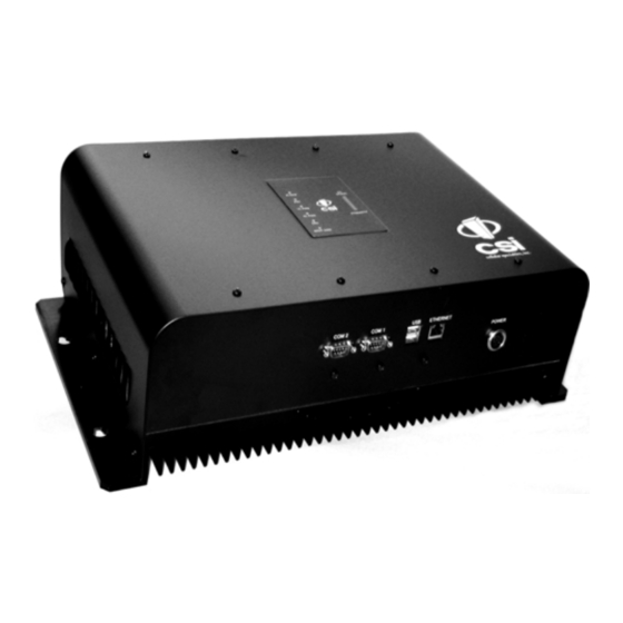
Page 7: Local Communication Interface Ports
LEDs on the front panel will light and go out several times. When boot is complete and no alarm conditions exist, none of the LED indicators will be illuminated. The CSI logo is illuminated when ever the repeater is powered. One or more bars on the LED bargraph may also be lit, depending on the strength of the signal being received from the donor site. -
Page 8: Monitoring & Alarms
In these cases it may not be practical to use the CSI-DSP85 for providing coverage to these sites. Selection of external attenuators to be used in line with the Antenna Port(s) -
Page 9: Donor Port
DONOR PORT If a CSI-DSP85 is installed in an area with very strong desired and/or undesired signals, it is important to ensure that the overall signal levels are optimized to be within the best operating range of the repeater. Additionally, de-sensing of a nearby base station site must be avoided. These goals can be accomplished by properly attenuating the antenna port(s) in the path of the donor antenna(s). -
Page 10: Wall Mounting The Digital Repeater
Wall Mounting the Digital Repeater The following diagram illustrates the best method for mounting the repeater to a wall in an typical installation. Note: for optimal cooling the unit should be mounted vertically on a wall with the antenna ports up. ITEM # PART # DESCRIPTION... -
Page 11: Important Installation Notes
Keyed for proper alignment, do not force connector into place. Optional Accessories A complete line of accessories is available from Cellular Specialties, Inc. Check with your CSI distributor for any additional items needed. Below are just a few examples suitable for most in-building needs. •UPS •Outside Donor Antenna... -
Page 12: Circuit Operational Description
Indoor Antennas continued To determine the quantity and locations of indoor antennas, use an appropriate phone's signal meter to determine areas of weak signals. These are the approximate areas where indoor antennas may be needed. Also be aware the signal from an indoor antenna, in most cases, can be expected to penetrate about two standard office sheetrock type walls to reach users. -
Page 13: Mechanical Specifications
Mechanical Specifications Parameter Specification Notes Repeater Size Height 4.69 in. Width 18.62 in. Depth 11.25 in. Box Weight 27.5 / 12.47 lbs/kg Box Thermal Management Convection cooled Large heatsink Surface Coating Powder Coat Color Satin Black Environmental Requirements Parameter Specification Notes Temperature Range 0 to +50 C... -
Page 14: Operating Power Parameters
Operating Power Parameters Parameter Specification Notes Maximum RF input Power +10 dBm without damage Linear Gain 85 dB Factory Calibrated Gain Pass Band Ripple +/-1.5 dB Automatic Gain Control (AGC) 30 dB max In 0.5 dB steps range Manual Gain Control 53.5-85 dB max In 0.5 dB steps Linear Output Power... -
Page 15: Mechanical Drawing
Mechanical Drawing TO INSIDE ANTENNA TO OUTSIDE ANTENNA ALARM UL PWR DL PWR POWER ETHERNET COM 1 COM 2 -16-... -
Page 16: System Status
Web based GUI Session Primary access to the repeater is gained using a LAN connection and a web browser program such as Firefox by Mozilla, or Internet Explorer from Microsoft. The repeater ships with the default IP address of 192.168.1.100, but it can be changed later if required. If connecting directly to the repeater from a laptop or PC with a crossover CAT-5E cable or over a LAN the user types the IP address of the repeater into the browser address line to connect. -
Page 17: Local Network
Local Network: If the user selects Local Network from the System Status page, the following screen is displayed and from here network configuration can be modified as required. The default is set to Static. Check with your IT department for explanation and approval of the DHCP and DHCP Server options you plan to use before you select them. -
Page 18: Program A Filter
The time required to complete this process will take just a few moments. Note: If the filter desired is not currently in the unit, additional filters along with instructions on how to load them are available by contacting CSI. -19-... -
Page 19: Remote Network
Remote Network: If the repeater includes a modem kit, click on Remote Network in the navigation box and the screen below is displayed. Highlight the carrier on whose network the repeater and modem will be configured and click the Change Settings button. Refer to the documentation included with the modem kit for addtional information on configuring the modem. -
Page 20: Install & Upload
Should a software install or upgrade be needed it can be done from the Install & Upload screen shown below. As with the other screens it can be reached by clicking the words in the navigation box. Contact CSI for updates and instructions. -21-... -
Page 21: Reboot
Reboot: Alarm Configuration: The Alarm Configuration page allows the user to specify what If a reboot of the repeater becomes events will trigger an alarm. necessary click on the Reboot option in the *NOTE: Letters, numbers & hyphens are the only navigation box and the Reboot page is acceptable nomenclature for the Location field and hyphens displayed. -
Page 22: Log Configuration
Log Configuration: The Log Configuration page provides the user with the means to modify three aspects of how log files are created and stored as shown below. To end the session exit the browser, the user will be automatically logged out. Text Menu Interface (Local Access) Local access to the repeater TMI, also known as the console interface, is made by connecting a serial cable (optional), as shown in figure 1, from the serial connector of the laptop to either of the serial ports on... -
Page 23: Terminal Emulation Program
Terminal Emulation Program Many terminal emulation programs will work if properly configured. In the following description, “TeraTerm” is used to establish the TMI session. This program is readily available via the Internet and is free from Ayera Technologies at: http://www.ayera.com/teraterm/ TeraTerm Pro Web works on Windows 95/98, 2000, XP. -
Page 24: Terminal Emulation Set-Up
Terminal Emulation Set-up Pressing “OK” will open up a blank dialog screen. Go to the setup dropdown menu and select Serial port to make changes to the serial port setup. Configure the terminal program for the correct COM port, in this case COM 1 and 115200 baud rate as shown below. -
Page 25: Tmi Login
TMI main menu will appear. Note: by default the Set Parameters option is disabled. To re-enable the user will press 1 and will be prompted for a username and password. The default user name is csi and the password is csi1234. The actions displayed are self-explanatory. - Page 26 Each “Set Parameter” selection, when chosen will be expanded to allow changing or setting of that parameter. For example from the Link Configuration menu on the previous page, selecting 1 - Adjust Gain will display the menu shown below. After selecting option 1, downlink, the current user gain is displayed and the option to change it is accomplished by typing the desired gain at the prompt.
-
Page 27: Telnet Session (Remote Access)
All the other options operate in much the same way. Some of the options will offer the user additional selections and will be self-explanatory. Below is one example of these additional options, the one shown below is the result of selecting (3) Filter Programming. Note: Graceful session termination is important. -
Page 28: Telnet Session Login
Telnet Session Login Pressing the “OK” button will bring the user to the following screen, which will require the user to log in. The default user name is “user”. The default password is “csi1234”. In the field after the prompt “DSP85-cell-X login;” type the user name and password. After typing the password press the enter key and the main menu will be displayed as shown next. -
Page 29: Modem Interface (Remote Access With Login)
A selection of modems is available as an option. If the modem requires a SIM card for activation, special requirements must be met for the SIM card to become fully functional, contact the service provider. In addition, an IP address must be obtained and entered into the CSI- DSP85-PSS8. -
Page 30: Additional Tips
Additional Tips Instructions to change TCP/IP settings on your Windows computer. Click in the Network Connections Icon in the Control Panel. See below. Right click on Local Area Connection - and select “Properties”. Scroll down to “Internet Protocol (TCP/IP) and click on the “Properties” button. -31-... - Page 31 If you are set up to use DHCP, the window shown below will be displayed. Select “Use the following IP address:” and enter “192.168.1.2.” The subnet mask should automatically populate to “255.255.255.0”. Nothing else will need to be chosen or entered. Click “OK”, then “OK again and retry connection.
-
Page 32: Suggested Spectrum Analyzer Setting
Suggested spectrum analyzer setting: When troubleshooting RF issues, and when surveying challenging RF environments, it’s important to have a spectrum analyzer capable of measuring the frequency that you are working with. An attenua- tor should be used to protect the input, when connected to a source of RF power such as the repeater or a powered DAS. -
Page 33: Industry Certifications/Registration Numbers
One Year Limited Warranty Seller warrants that its products are transferred rightfully and with good title; that its products are free from any lawful security interest or other lien or encumbrance unknown to Buyer; and that for a period of one year from the date of installation or fifteen months from the date of original ship- ment, whichever period expires first, such products will be free from defects in material and workmanship which arise... -
Page 34: Index
RF issues 33 13, 18, 19, 20, 21, 22 Connectors 15 Manual Gain Control 15 CPU 5 Maximum RF input Power 15 CSI 5 Modem Interface 30 UHCI 5 modulation selection 19 UL PWR 7 Monitoring & Alarms 9... - Page 35 Notes -36-...
- Page 36 Notes -37-...
- Page 37 Notes -38-...
- Page 38 Notes -39-...
- Page 39 960-1041-009 rev A ECO 2266...
Need help?
Do you have a question about the CSI-DSP85-L7AB and is the answer not in the manual?
Questions and answers