
Subscribe to Our Youtube Channel
Related Manuals for CSI CSI-DSP85-250-AW


Summary of Contents for CSI CSI-DSP85-250-AW
- Page 1 CSI-DSP85-250-AW, CSI-DSP85-251-AW, CSI-DSP85I-250-AW, CSI-DSP85I-251-AW, CSI-DSP85-250-S-AW, CSI-DSP85-251-S-AW, CSI-DSP85I-250-S-AW, and CSI-DSP85I-251-S-AW Installation Manual...
-
Page 3: Table Of Contents
Table of Contents Product Registration Information ......................... 4 Document Purpose / Intended Users ........................4 Application ................................. 4 Safety Guidelines ............................... 4 Important Safety Information ..........................5 Terms Used in This Manual ..........................5 Product Introduction ............................5 Band Plans ................................ 6 Filter File Naming Conventions ........................... -
Page 4: Product Registration Information
DISCLAIMER: All information and statements contained herein are accurate to the best of the knowledge of Cellular Specialties, Inc. (CSI), but Cellular Specialties makes no warranty with respect thereto, including without limitation any results that may be obtained from the products described herein or the infringement by such products of any proprietary rights of any persons. -
Page 5: Important Safety Information
The filter set configurations stored in memory determine the unit’s adaptability to various field applications. The following pages describe the PCS band plan as well as the convention CSI uses to identify and store the files that make up the filter set. All units are shipped with an active filter set that is programmed according to the ordering parties’... -
Page 6: Band Plans
Band Plan CSI’s DSP AWS-1 Band Plan Mobile Mobile (MHz) (MHz) 1710 1720 1730 17 35 1 740 1745 17 55 2 110 2120 2130 21 35 21 40 2145 2155 B ase Bas e (MHz) (MHz) U L1710-1720 U L1720-1730... -
Page 7: Filter File Naming Conventions
Filter File Naming Convention Note: Filter file names will be from six to twelve characters long. Each character position in the filter file name is used to define the characteristics of the filter as shown above. All frequencies are shown in MHz - 7 -... -
Page 8: Led Indicator
Functional Overview CSI digital repeaters incorporates the following features for convenient operation, access, protection, and control. • Network Configuration and Control using either a webpage style GUI through any standard browser or a menu driven user interface using the serial port. -
Page 9: Local Communication Interface Ports
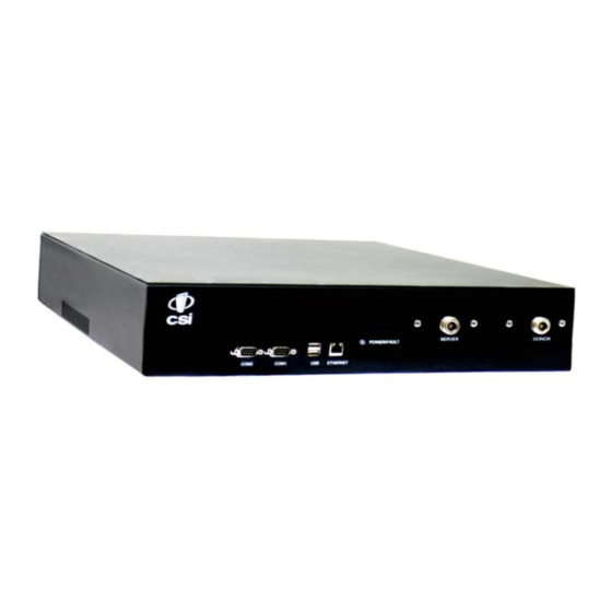
Local Communication Interface Ports To allow monitoring and control, the repeater is equipped with four ports that provide external communication access (1 Ethernet CAT-5, 2 DB-9 serial, and 1 USB). The Ethernet, CAT-5 port is provided as a primary communications port to the PC. One serial interface provides commu- nications to local PC and the second to an external modem when provided. -
Page 10: System Set-Up Considerations
System Set-Up Considerations All cables should be checked for shorts and opens. Also verify that there are no cables with loose or poor connections. RF leakage could cause oscillation to occur under some conditions. The rooftop antenna (Donor Antenna), if directional, should be checked for proper alignment along the calculated compass heading. -
Page 11: Attenuator Selection Guidelines
Attenuator Selection Guidelines: Accurate attenuator values need to be chosen to ensure that the maximum total power (higher of Composite or In- Band Input) applied to the donor and server port(s) does not exceed the following thresholds: Input Signal Max Gain Input Signal Max Gain <-45 dBm... -
Page 12: Mounting The Digital Repeater
Brackets are provided for both options. Note: Dual and single band modules are shown for illustration purposes. Rack mount of the repeaters requires just two brackets mounted to the front corners of each module. Note: the CSI digital repeaters must be supported in the rack system with a shelf or slide rail. -
Page 13: Optional Accessories
Optional Accessories A complete line of accessories is available from Cellular Specialties, Inc. Check with your CSI distributor for any additional items needed. Below are just a few examples suitable for most in-building needs. •Outside Donor Antenna •UPS AWS - model number: CSI-AP/806-2.5K/7-10... -
Page 14: Functional Block Diagram
Functional Block Diagram -14 -... -
Page 15: Mechanical Specifcations
Mechanical Specifcations Parameter Specification Notes Repeater Size Height 3.48 in. Width 19.00 in. Depth 18.00 in. Box Weight 11.6lbs / 5.3 kg Box Thermal Management Fan cooled Surface Coating Powder Coat Color Satin Black AC Power Specifcations Parameter Specification Notes AC Voltage 100 - 240 VAC External Power Supply... -
Page 16: Operating Power Parameters
Manual Gain Control 53.5-85 dB max In 0.5 dB steps Linear Output Power + 27dBm max Uplink and Downlink **AGC Set Point (CSI-DSP85-250-AW&CSI-DSP85I-250-AW) AWS +25dBm ** (CSI-DSP85-250-S-AW&CSI-DSP85I-250-S-AW) Linear Output Power + 30dBm max Uplink and Downlink **AGC Set Point (CSI-DSP85-251-AW&CSI-DSP85I-251-AW) AWS +28dBm ** (CSI-DSP85-250-S-AW&CSI-DSP85I-250-S-AW) -
Page 17: Mechanical Drawing
Mechanical Drawing -17 -... -
Page 18: System Status
Web based GUI Session Primary access to the repeater is gained using a LAN connection and a web browser program such as Firefox by Mozilla, or Internet Explorer from Microsoft. The repeater ships with the default IP address of 192.168.1.100, but it can be changed later if required. If connecting directly to the repeater from a laptop or PC with a crossover CAT-5E cable or over a LAN the user types the IP address of the repeater into the browser address line to connect. -
Page 19: Local Network
Local Network: If the user selects Local Network from the System Status page, the following screen is displayed and from here network configuration can be modified as required. The default is set to Static. Check with your IT department for explanation and approval of the DHCP and DHCP Server options you plan to use before you select them. -
Page 20: Program A Filter
The time required to complete this process will take just a few moments. Note: If the filter desired is not currently in the unit, additional filters along with instructions on how to load them are available by contacting CSI. - 20 -... -
Page 21: Remote Network
Remote Network: If the repeater includes a USB modem kit, click on Remote Network in the navigation box and the screen below is displayed. Highlight the carrier on whose network the repeater and modem will be configured and click the Change Settings button. Refer to the documentation included with the modem kit for addtional information on configuring the modem. -
Page 22: System Health
Should a software install or upgrade be needed it can be done from the Install & Upload screen shown below. As with the other screens it can be reached by clicking the words in the navigation box. Contact CSI for updates and instructions. - 22 -... -
Page 23: Reboot
Reboot: Alarm Configuration: The Alarm Configuration page allows the user to specify what If a reboot of the repeater becomes events will trigger an alarm. necessary click on the Reboot option in the *NOTE: Letters, numbers & hyphens are the only navigation box and the Reboot page is acceptable nomenclature for the Location field and hyphens displayed. -
Page 24: Log Configuration
A word of warning here, be careful when setting the new password. If you forget what you set your password to you’ll need to contact CSI at 1-877-844-4274 for assistance. -
Page 25: Text Menu Interface (Local Access)
Text Menu Interface (Local Access) Local access to the repeater TMI, also known as the console interface, is made by connecting a serial cable (optional), as shown in figure 1, from the serial connector of the laptop to either of the serial ports on the bottom end panel of the repeater. - Page 26 Select the Serial radio button and press OK as shown below. Note: It may be necessary, in the System Properties section of the control panel; using Device Manager to determine what COM port your computer uses for the communications port. In this case it is COM 1.
- Page 27 TMI main menu will appear. Note: by default the Set Parameters option is disabled. To re- enable the user will press 1 and will be prompted for a username and password. The default user name is csi and the password is csi1234. The actions displayed are self-explanatory.
- Page 28 Each “Set Parameter” selection, when chosen will be expanded to allow changing or setting of that parameter. For example from the Link Configuration menu on the previous page, selecting 1 - Adjust Gain will display the menu shown below. After selecting option 1, downlink, the current user gain is displayed and the option to change it is accomplished by typing the desired gain at the prompt.
-
Page 29: Telnet Session (Remote Access)
All the other options operate in much the same way. Some of the options will offer the user additional selections and will be self-explanatory. Below is one example of these additional options, the one shown below is the result of selecting (3) Filter Programming. Note: Graceful session termination is important. - Page 30 Pressing the “OK” button will bring the user to the following screen, which will require the user to log in. The default user name is “user”. In the field after the prompt type the user name. The default password is “csi1234”. After typing the password press the enter key and the main menu will be displayed as shown next.
-
Page 31: Modem Interface (Remote Access With Login)
Telnet and serial sessions both provide access to the same Text Menu Interface. We have already shown many of the options available and all are self explanatory, so they will not be repeated. Modem Interface (Remote Access with login) A modem can also be used to gain remote access to the unit provided the repeater has been properly equipped. -
Page 32: Additional Tips
Additional Tips Instructions to change TCP/IP settings on your Windows computer. Click in the Network Connections Icon in the Control Panel. See below. Right click on Local Area Connection - and select “Properties”. Scroll down to “Internet Protocol (TCP/IP) and click on the “Properties” button. - 32 -... - Page 33 If you are set up to use DHCP, the window shown below will be displayed. Select “Use the following IP address:” and enter “192.168.1.2.” The subnet mask should automatically populate to “255.255.255.0”. Nothing else will need to be chosen or entered. Click “OK”, then “OK again and retry connection.
-
Page 34: Suggested Spectrum Analyzer Setting
Suggested Spectrum Analyzer Setting: When troubleshooting RF issues, and when surveying challenging RF environ- ments, it’s important to have a spectrum analyzer capable of measuring the frequency that you are working with. An attenuator should be used to protect the input, when connected to a source of RF power such as the repeater or a powered DAS. -
Page 35: Warranty
Warranty One Year Limited Warranty Seller warrants that its products are transferred rightfully and with good title; that its products are free from any lawful security interest or other lien or encumbrance unknown to Buyer; and that for a period of one year from the date of installation or fifteen months from the date of original shipment, which- ever period expires first, such products will be free from defects in material and workmanship which arise under proper and normal use and service. -
Page 36: Index
Log Configuration 24 Color 15 login 18 UHCI 5 Connectors 16 USB 5 CPU 5 USB Interface 9 CSI 5 Manual Gain Control 16 Maximum RF input 16 Mechanical Drawing 17 Wall Mounting 12 DAS 5 Modem Interface 31 Warranty 35 Depth 15 Monitoring &... - Page 37 Notes - 37 -...
- Page 38 Notes - 38 -...
- Page 39 Notes - 39 -...
- Page 40 960-1041-013 rev A ECO2356...
Need help?
Do you have a question about the CSI-DSP85-250-AW and is the answer not in the manual?
Questions and answers