Table of Contents
Advertisement
Advertisement
Table of Contents
Troubleshooting

Related Manuals for U-Line HNB315


Summary of Contents for U-Line HNB315
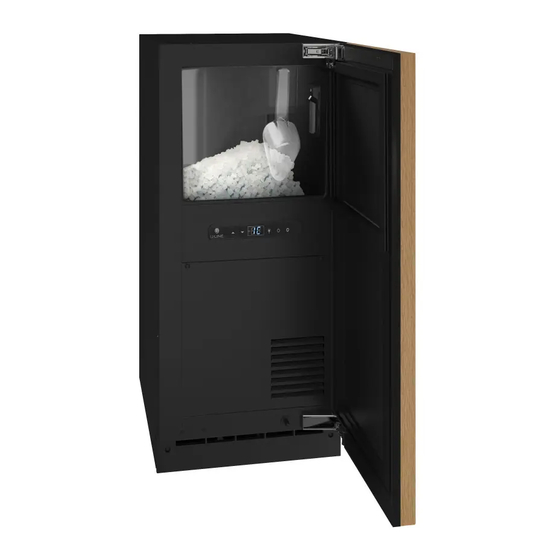
- Page 1 USER GUIDE & SERVICE MANUAL 3 Class UHNB315 / UHNP315 15” Nugget Ice Machine ● ●...
- Page 2 USER GUIDE u-line.com SAFETY • INSTALLATION & INTEGRATION • OPERATING INSTRUCTIONS • MAINTENANCE • SERVICE Contents Intro Extended Non-Use Safety Service Safety and Warning Quick Guide Disposal and Recycling Troubleshooting Disposal And Recycling Wire Diagram Reference Diagrams Installation Product Liability...
-
Page 3: Product Information
1. U-Line Customer Care must be contacted immediately at +1.800.779.2547. 2. Service or repairs performed on the unit without prior written approval from U-Line is not permitted. If the unit has been altered or repaired in the field without prior written approval from U-Line, claims will not be eligible. -
Page 4: Safety And Warning
USER GUIDE u-line.com Safety and Warning DANGER NOTICE This unit contains R600a (Isobutane) which is a Please read all instructions before installing, flammable hydrocarbon. It is safe for regular operating, or servicing the appliance. use. Do not use sharp objects to expedite defrosting. -
Page 5: Disposal And Recycling
USER GUIDE u-line.com Disposal and Recycling DANGER RISK OF CHILD ENTRAPMENT. Before you throw away your old refrigerator or freezer, take off the doors and leave shelves in place so children may not easily climb inside. If the unit is being removed from service for disposal,... - Page 6 USER GUIDE u-line.com Disposal and Recycling DANGER RISK OF CHILD ENTRAPMENT. Before you throw away your old refrigerator or freezer, take off the doors and leave shelves in place so children may not easily climb inside. If the unit is being removed from service for disposal,...
-
Page 7: Environmental Requirements
USER GUIDE u-line.com Environmental Requirements This model is intended for indoor/interior applications only and is not to be used in installations that are open/ exposed to natural elements. This unit is designed to operate between 50°F (10°C) and 100°F (38°C). Higher ambient temperatures may reduce the unit’s ability to reach low temperatures and/or reduce... - Page 8 USER GUIDE u-line.com Electrical WARNING SHOCK HAZARD — Electrical Grounding Required. Never attempt to repair or perform maintenance on the unit until the electricity has been disconnected. Never remove the round grounding prong from the plug and never use a two-prong grounding adapter.
-
Page 9: Cutout & Product Dimensions
14 ⁄ ” (379 mm) PREPARE SITE Your U-Line product has been designed for either free- standing or built-in installation. When built-in, your unit does not require additional air space for top, sides, or rear. However, the front grille must NOT be obstructed, 28”... -
Page 10: Side-By-Side Installation
USER GUIDE u-line.com Side-by-Side Installation Hinge-by-Hinge Installation (Mullion) When installing two units hinge-by-hinge, 13/16" (22 mm) OTHER SITE REQUIREMENTS is required for integrated models. Additional space may be Side-by-Side Installation needed for any knobs, pulls or handles installed. Units must operate from separate, properly grounded electrical receptacles placed according to each unit’s... -
Page 11: Water Hookup
The water valve uses a standard 1/4" (6.35 mm) is under pressure at all times. Plastic may crack compression fitting. U-Line recommends using accessory or rupture with age and cause damage to your water hook up kit – part # 80-54674-00. The kit includes a home. - Page 12 USER GUIDE u-line.com 1. Turn off water supply and disconnect electrical supply to 5. Turn on water supply and check for leaks. product prior to attempting installation. 6. Reinstall back panel. 2. Remove the back panel. 3. Thread water line through back panel hole (with bushing).
-
Page 13: Gravity Drain
DRAIN CONNECTION CAUTION With Trap and Vent Proper Drain If your U-Line unit did not come with a factory installed drain pump you must use a gravity A gravity drain may be used if: style drain connection. For assistance in Drain line has at least a 1"... -
Page 14: Factory Installed Drain Pump
(Optional Hook-Up) spigot assembly, or does not otherwise meet the requirements for a gravity drain, you may have ordered a pre-installed U-Line P60 drain pump. Waste If you need to install a P60 drain pump into your unit, see Valve DRAIN PUMP section in the User Manual. -
Page 15: Anti-Tip Bracket
USER GUIDE u-line.com Anti-Tip Bracket Surrounding area (Top view) Use one of the methods below to secure the unit CABINET/COUNTER ANTI-TIP INSTALLATION (For built-in applications) Back of unit Back wall Slide unit out so screws on front of unit are easily accessible. -
Page 16: General Installation
USER GUIDE u-line.com General Installation INSTALLATION 1. Plug in the power/electrical cord. LEVELING INFORMATION 1. Use a level to 2. Gently push the unit into position. Be careful not to confirm the unit is entangle the cord or water and drain lines, if level. -
Page 17: Integrated Panel Dimensions
USER GUIDE u-line.com Integrated Panel Dimensions Integrated Panel Dimensions Metric measurements rounded and optimized. INTEGRATED PANEL BACK SURFACE MUST HAVE AMPLE FLAT SURFACE TO MOUNT OVERLAY PANEL FLAT AND WITHOUT " INTERFERENCE (20 mm) NOTICE Due to differences in surrounding cabinetry the "... - Page 18 USER GUIDE u-line.com HANDLELESS INTEGRATED DOOR PANEL 3. Prepare the insert(s) that will back up the handleless design. Wooden Insert – Cut 1/8" (3 mm) thick The following procedure is designed to provide a finished, wooden insert(s) to the dimensions below.
- Page 19 USER GUIDE u-line.com Handleless Integrated Panel Dimensions " (3 mm) Top Design " (6 mm) " (22 mm) Ref. " " (R 16 mm) (60 mm) " (379 mm) " (70 mm) Insert Notch " (70 mm) Wooden Insert Notch Depth: "...
- Page 20 USER GUIDE u-line.com EXTENDED INTEGRATED PANEL 3. Optional: Install handles and hardware NOTICE Due to differences in surrounding cabinetry the NOTICE panel may not perfectly align with door. The The door panel must not weigh more than 20 lbs procedure below is designed to provide a (10 kg).
- Page 21 Extended Integrated Panel Dimensions Integrated Grille If you would like to cover the grille with an integrated BACK SURFACE MUST HAVE AMPLE FLAT SURFACE TO MOUNT OVERLAY PANEL FLAT AND WITHOUT panel, purchase U-Line’s adjustable grille accessories. " INTERFERENCE (20 mm) "...
-
Page 22: Integrated Panel Installation
11.Remove clamps from door. panel to door using Clamp clamps. A robust tape may also be NOTICE used. U-Line If panel requires additional adjustment after recommends the removing clamps, slightly loosen each screw and use of bar clamps Door/Drawer adjust panel as necessary. Tighten screws upon to secure the panel completion. -
Page 23: Grille Installation
USER GUIDE u-line.com Grille Installation REMOVING AND INSTALLING GRILLE WARNING Disconnect electric power to the unit before removing the grille. When using the unit, the grille must be installed. WARNING DO NOT touch the condenser fins. The condenser fins are SHARP and can be easily damaged. -
Page 24: Door Swing
USER GUIDE u-line.com Door Swing Wall For Integrated models that are installed adjacent to a wall, 1/2" (13 mm) 1/2" (13 mm) clearance is recommended from wall on hinge side to allow the door to open 90°. Allow for additional space for any knobs or pulls installed on the integrated panel/frame. -
Page 25: Door Alignment And Adjustment
USER GUIDE u-line.com Door Adjustments REVERSING THE DOOR Open door. DOOR ALIGNMENT AND ADJUSTMENT Using T-25 Torx bit loosen screw #1 and remove screw Align and adjust the door if it is not level or not sealing #2 on top and bottom hinge. Slide and remove the properly. -
Page 26: First Use
Initial startup requires no adjustments. See CONTROL OPERATION section for more details. NOTICE U-Line recommends discarding the ice produced during the first two to three hours of operation to avoid possible dirt or scale that may dislodge from the water line. -
Page 27: Control Operation
USER GUIDE u-line.com Control Operation CONTROL FUNCTION GUIDE FUNCTION COMMAND NOTES ON/OFF Press and release Unit will immediately turn ON or OFF Adjust ice density See “Ice” section Option Open Door White While holding press and release Adjust light color... - Page 28 The factory default ice setting is 0, which produces a firm and compact ice nugget. U-Line’s exclusive U-Choose™ ice adjustability feature allows you five levels of adjustment from 0 to -5. At -5 the ice is soft and chewable.
-
Page 29: Airflow And Product Loading
USER GUIDE u-line.com Airflow and Product Loading NOTICE The unit requires proper airflow to perform at its highest efficiency. Do not block the front grille at any time, or the unit will not perform as expected. Do not install the unit behind a door. -
Page 30: Exterior Cleaning
USER GUIDE u-line.com Cleaning Using abrasive pads such as ScotchBrite™ will cause the graining in the stainless steel to EXTERIOR CLEANING become blurred. Vinyl Clad (Black or White) Models Clean surfaces with a mild detergent and warm water Rust not cleaned up promptly can penetrate the solution. - Page 31 Vent Tube and Funnel Clean water SafeCLEAN Plus™ Cleaner (Part No. 80-55266-00) – included with unit Dispenser Need more cleaner? Visit u-line.com. Tube CAUTION Press and release will appear in the display Use only SafeCLEAN Plus Cleaner. Use of any b.
-
Page 32: Water Filter
The filter must remain in place when using the machine. The filter, part # 80-55-268-00, should be replaced every 6 to 12 months. See your dealer or u-line.com for replacement filters. To remove filter, press and rotate counterclockwise approximately turn. -
Page 33: Cleaning Condenser
USER GUIDE u-line.com Cleaning Condenser INTERVAL - EVERY SIX MONTHS To maintain operational efficiency, keep the front grille free of dust and lint, and clean the condenser when necessary. Depending on environmental conditions, more or less frequent cleaning may be necessary. -
Page 34: Extended Non-Use
USER GUIDE u-line.com Extended Non-Use VACATION/HOLIDAY, PROLONGED SHUTDOWN For questions regarding winterization, please call U-Line at 800.779.2547. The following steps are recommended for periods of extended non-use: CAUTION 1. Remove all consumable content from the unit. Damage caused by freezing temperatures is not 2. -
Page 35: Service Menu
USER GUIDE u-line.com Quick Guide Model number SERVICE MENU 22. Light All Segments Exit 23. Activate Defrost/Harvest- press and hold for 3 Thermistor 1 temperature not including offsets. seconds to activate defrost/harvest Thermistor 2 temperature not including offsets. 24. Defaults- press and hold for 3 seconds to restore all values to factory defaults. Thermistor 3 temperature not including offsets. 25. Main Software (Display only) Thermistor 4 temperature not including offsets. 26. Live Log Period (frequency that data is output Thermistor 1 offset. (+/- 10) to diagnostics port) Thermistor 2 offset. (+/- 10) 27. Factory test mode (0=Off, 1=On) Thermistor 3 offset. (+/- 10) 28. Compressor RPM Thermistor 4 offset. (+/- 10) 29. Freeze time adjust (Model 54 only) Thermistor 2 set point 30. - Page 36 Hold Light button for 5 seconds to enter. Tap Light button to exit. Service Mode Hold down Hidden button (U-Line logo) to enter. Scroll through options with Up and Down buttons. 3 Hour Shutoff Mode Hold Down button and Power button for 5 seconds to enter Silent Mode on select models.
-
Page 37: Before Calling For Service
Find a Servicer page to locate a U-Line Authorized servicer. If your product is in Troubleshooting - What to check when problems occur: warranty please make sure to register it at www.U-Line.com/u-lineregistration. -
Page 38: Wire Diagram
USER GUIDE u-line.com Wire Diagram Wire Diagram... -
Page 39: Reference Diagrams
USER GUIDE u-line.com Reference Diagrams Remove M6 socket head allen screw Remove compression nozzle retainer DISASSEMBLE EVAPORATOR MODULE Remove compression nozzle Remove Gear Motor and Auger Unplug the gear motor (three connectors) Remove ground screw connection. Remove main housing •... - Page 40 USER GUIDE u-line.com Reference Diagrams Install compression nozzle Evaporator • Remove and inspect compression nozzle O-ring seal - replace if damaged in any way Remove and inspect main housing O-ring seal. Re- • Clean O-ring groove. Lubricate O-ring with Petrol-gel place if damaged in any way and reinstall.
- Page 41 USER GUIDE u-line.com 11. Use screwdriver to orient auger shaft to align with 16. Install screw and tighten motor shaft keyway 12. Install key into keyway 17. Plug in gear motor • BLUE to BLUE 13. Install spacer, ensure that key is captured in slot •...
-
Page 42: Product Liability
The part that caused the damage must be returned to U-Line in its entirety. The part must be clearly labeled with the serial number of the unit it was removed from, the date, and the servicer who removed the part. -
Page 43: Warranty Claims
Claims must be submitted online at • Final billing - Remodel www.U-LineService.com Warranty parts will be shipped at no charge after U-Line • 60 day submittal deadline from date of completed confirms warranty status. Please provide the model, serial service number, part number and part description. - Page 44 USER GUIDE u-line.com Parts UHNB315-IS01A ACCESS PANEL ASSY, NUGGET 80-55369-00 BACK PANEL, NUGGET 80-55377-00 COMPRESSOR W/ELECTRICALS 80-55211-00 CONDENSER ASSY, NUGGET 315 80-55379-00 CONDENSER FAN MOTOR 80-54138-00 COVER W/HOOK, BLACK 80-54072-00 DISPLAY MODULE 80-55214-00 DOOR ASSY, NUGGET INT 315 80-55384-00 DRIER 80-54055-00 DUMP VALVE ASSY, NUGGET 15"...
-
Page 45: Ordering Replacement Parts
Warranty parts will be shipped at no charge after U-Line confirms warranty status. Please provide the model, serial number, part number and part description. Some parts will require color or voltage information. - Page 46 Never use a torch on a fully charged refrigeration system. Never substitute U-Line OEM replacement parts or methods of construction. R-600a must be stored and transported in Technician must observe all federal, state and local laws regarding refrigerants.
- Page 47 USER GUIDE USER GUIDE u-line.com u-line.com SAFETY • INSTALLATION & INTEGRATION • OPERATING INSTRUCTIONS • MAINTENANCE • SERVICE R-600A SPECIFICATIONS/LABELING WARNING R-600a equipped products are labeled (both the unit and the compressor). Only skilled and well trained service technicians permitted to service R-600a equipped products.
-
Page 48: Leak Detection
USER GUIDE USER GUIDE u-line.com u-line.com SAFETY • INSTALLATION & INTEGRATION • OPERATING INSTRUCTIONS • MAINTENANCE • SERVICE Evacuate/reclaim via the piecing pliers to ensure the When re-brazing, the system must be purged with dry system is empty of R-600a before any system work is nitrogen and at least one access point open to the performed. - Page 49 USER GUIDE USER GUIDE u-line.com u-line.com SAFETY • INSTALLATION & INTEGRATION • OPERATING INSTRUCTIONS • MAINTENANCE • SERVICE The low side of the refrigeration system (evaporator, Proper ventilation during service is required. compressor and suction line) must be leak tested with the compressor off (equalized pressure).
-
Page 50: System Diagnosis Guide
USER GUIDE u-line.com System Diagnosis Guide REGRIGERATION SYSTEM DIAGNOSIS GUIDE System Suction Suction Compressor Condenser Capillary Evaporator Wattage Condition Pressure Line Discharge Tube Normal Normal Slightly Very hot Very hot Warm Cold Normal below room temperature Overcharge Higher than Very cold... -
Page 51: Compressor Specifications
USER GUIDE u-line.com Compressor Specifications FMXA9C REFRIGERANT R600A DANGER VOLTAGE 230 VAC FREQUENCY 43-134 Hz START WINDING 20 Ohm at 77 Electrocution can cause death or serious injury. RUN WINDING 20 Ohm at 77 Burns from hot or cold surfaces can cause serious injury. -
Page 52: Troubleshooting - Extended
DC outputs located on the relay/power board. Included in this section are some diagnostic tips and of course, if additional help is required, please contact the U-Line Corp, “Customer Care Facility” at +1.800.779.2547 for assistance. NORMAL OPERATING SOUNDS All models incorporate rigid foam insulated cabinets to provide high thermal efficiency and maximum sound reduction for its internal working components. -
Page 53: Main Control
Go to component testing and turn on fill valve and verify Production 120V at the valve. Low Ice Dirty evaporator, dirty condenser, faulty Clean the evaporator using U-Line cleaner, clean the Production bin thermistor condenser coil if needed, check bin thermistor reading in service mode. -
Page 54: Error Codes
USER GUIDE u-line.com Relay & DC Outputs PLUNGER SWITCH A plunger switch is used to monitor door state. When the One of the primary functions of the main control is to door is closed it comes into contact with the plunger which operate the multiple relay and DC outputs during each closes a circuit which turns the light and display off. - Page 55 USER GUIDE u-line.com Control Operation-Service CONTROL FUNCTION GUIDE FUNCTION COMMAND DISPLAY/OPTIONS UI BUTTON LAYOUT and release Unit will immediately Press ON/OFF turn ON or OFF Sabbath Mode See “Sabbath Mode” section Silent Mode (ice production Display will shw “3H” Hold...
-
Page 56: View Error Log
USER GUIDE u-line.com SERVICE MODE GUIDE SERVICE MODE GUIDE 0. Exit THERMISTOR 1 - BIN 1. Thermistor 1 temperature not including offsets. This shows the pure thermistor reading with no off- 2. Thermistor 2 temperature not including offsets. sets taken into account. - Page 57 USER GUIDE u-line.com 15. CLEAR ERROR LOG To clear errors, press and hold (5 seconds) when CLR is flashing. 16. THERMISTOR - 1 DIFFERENTIAL This number should not be adjusted 17. Does not apply to this model 18. Does not apply to this model 19.
-
Page 58: Model List
MODEL NUMBER 1. Disconnect the unit from power source. 2. Push and hold the U-Line button. 3. While still holding the U-Line button, plug the unit into the appropriate power source. 4. When the flashing digits appear (3-5 seconds), use the up and down arrow buttons to select the appropriate model number*. - Page 59 USER GUIDE u-line.com Control Operation-Service...
- Page 60 USER GUIDE u-line.com Thermistor Thermistor Resistance Data Nominal Resistance Thermistors are used for various temperature readings. Temp (F) Temp (C) (OHMS)* Thermistors provide reliable temperature readings using a 169157 resistance which varies based on surrounding temperatures. 121795 If a faulty thermistor is suspected, it may be tested using 88766 an accurate ohmmeter.
- Page 61 One Year Limited Warranty For one year from the date of original purchase, this U-Line product warranty covers all parts and labor to repair or replace any part of the product that proves to be defective in materials or workmanship. For products installed and used for normal residential use, material cosmetic defects are included in this warranty, with coverage limited to 60 days from the date of original purchase.
Need help?
Do you have a question about the HNB315 and is the answer not in the manual?
Questions and answers