Advertisement
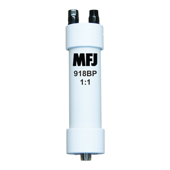
MFJ-918BP, MFJ-2919BP, and MFJ-2920BP
1.5 kW, 1.8-30 MHz Portable Balun
Introduction: Without a balun, the outer surface of your coax shield provides a
common-mode path for transmitted RF to flow from the antenna down to your
operating location. Here, it can disrupt or damage sensitive electronics and, if
severe, may even change the antenna's radiation pattern, distort your transmit
audio, or cause a painful RF burn. On receive, the process is reversed, with stray
locally generated carriers and "hash" traveling up the cable to the feedpoint to
raise the noise floor and cover weak signals.
Description: The MFJ-918BP, MFJ-2919BP, and MFJ-2920BP are especially
packaged to provide balun protection for portable installations. Antenna wire or
ladder line is connected to the PVC housing using color-coded 5-way binding
posts for rapid installation and removal. Color coded terminals indicates the DC
path through the MFJ-918BP (red = center conductor, black = shield). Note that
the MFJ-2919BP and MFJ-2920BP have internal transformer connections that
appear as a DC short between antenna terminals. On the inside, high-
permeability ferrite beads are installed over RG-303 Teflon coax to ensure high
power handling, maximum suppression, and minimal signal loss. Chemically
welded PVC construction guarantees long life under adverse environmental
conditions. Coax attaches to a premium grade Teflon SO-239.
Models:
[ ] MFJ-918BP: A 1:1 ratio 50-Ohm current balun designed to minimize losses
and deliver superior suppression over the entire HF range. Dipole or G5RV feed
connects directly to 5-way terminals.
[ ] MFJ-2919BP: A 4:1 ratio transmission-line transformer style balun designed
for 200-Ohm loads. Especially adapted for portable folded dipoles and OCFDs.
[ ] MFJ-2920BP: A 9:1 ratio transmission-line transformer design for 450-Ohm
applications. May also be used for transitions to ladder line.
Installation:
The PVC balun enclosure may be secured with a hose clamp, taped, or tethered
to any portable mast, post, or tower to serve as a center insulator for a temporary
antenna. When installing, always support the balun enclosure vertically with the
weep hole facing toward the ground to ensure proper drainage.
Important Warning: To prevent accidental death or serious injury, never
install an antenna where it can contact power lines. Also, to prevent
dangerous RF burns, keep energized antenna surfaces out of reach to
humans and animals.
Advertisement
Table of Contents

Related Manuals for MFJ MFJ-918BP


Summary of Contents for MFJ MFJ-918BP
- Page 1 PVC housing using color-coded 5-way binding posts for rapid installation and removal. Color coded terminals indicates the DC path through the MFJ-918BP (red = center conductor, black = shield). Note that the MFJ-2919BP and MFJ-2920BP have internal transformer connections that appear as a DC short between antenna terminals.
- Page 2 ONTH ARRANTY MFJ Enterprises, Inc. warrants to the original owner of this product, if manufactured by MFJ Enterprises, Inc. and purchased from an authorized dealer or directly from MFJ Enterprises, Inc. to be free from defects in material and workmanship for a period of 12 months from date of purchase provided the following terms of this warranty are satisfied.
Need help?
Do you have a question about the MFJ-918BP and is the answer not in the manual?
Questions and answers