Advertisement
Quick Links
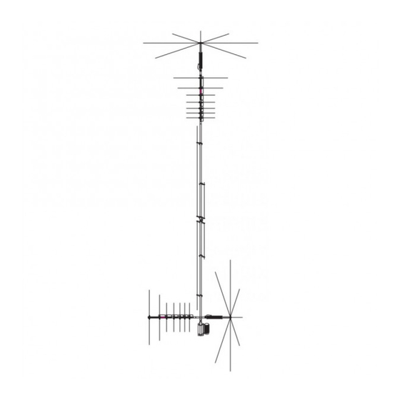
MFJ-1799
2,6,10,12,15,17,20,30,40,80 METER
Vertical Antenna
INSTRUCTION MANUAL
CAUTION: Read All Instructions
Before Operating Equipment
300 Industrial Park Road
Starkville, MS 39759 USA
Tel: 662-323-5869 Fax: 662-323-6551
COPYRIGHT
2013 MFJ Enterprises Inc.
C
Advertisement

Related Manuals for MFJ MFJ-1799


Summary of Contents for MFJ MFJ-1799
- Page 1 MFJ-1799 2,6,10,12,15,17,20,30,40,80 METER Vertical Antenna INSTRUCTION MANUAL CAUTION: Read All Instructions Before Operating Equipment 300 Industrial Park Road Starkville, MS 39759 USA Tel: 662-323-5869 Fax: 662-323-6551 COPYRIGHT 2013 MFJ Enterprises Inc.
- Page 2 Introduction Thank you for purchasing the MFJ-1799 vertical HF antenna. You new antenna is composed of High strength 6063 aircraft aluminum for excelent rigidy and light weight. Silver plated wire with Teflon insulation is use on a fiberglass core to ensure low resistance and high power handling capablility on each loading section.
- Page 3 Assembly Before you begin assembly, find a place suitable for antenna construction. This area should be free of power lines and obstructions so that you may move the antenna freely. It is best that the area be a flat level surface to allow you to lay the antenna on its side using saw horses or some other type of support.
- Page 4 Stub Assembly Parts needed for this assembly 8. Two double brackets made out of aluminum 9. Twelve 6-32 x ½ phillips head screws 10. Twenty four 6-32 nuts with built in lock washers. 11. Four single brackets made out of ABS plastic 12.
- Page 5 Base Bracket Assembly Loosely assemble the base bracket using the hardware as shown. 18 Smaller U-bolt (Antenna side) 19 Smaller saddle (Antenna side) 20 Base bracket 21 Larger saddle (Mast side) 22 Larger U-bolt (Mast side) 23 5/16 Split washer 24 5/16 Hex Nut Slide the Mast bracket onto the bottom of the antenna.
- Page 6 Cross Tube Disassemble the U-bolt set and attach the cross tube to the main radiator just above the bolt at the bottom insulator. About ½ inch above the Top View bolt will be fine. Orentation of the cross tube does not matter 25 U-bolt set 26 Cross tube 27 Balun Assembly...
- Page 7 Loosely fit the 6-32 x ½ screws and nuts into the rings. 6-32 x ½ Insert the rods into the ring and tighten the screws. The rings are shown further apart than they are on the loading section for illustration only. You do not need to unbolt them from the tube.
- Page 8 Install the 80 meter spokes (48 inches) into the 80 meter loading coil ring. This ring requires 8 rods per ring. The two 80 meter loading coils are the same so it doesn’t matter which one is on top or bottom. 36 Sixteen 48 inch rods 9 Twelve 6-32 x ½...
- Page 9 Spokes not shown Slip a #10 hose clamp over each end of the cross tube. Slide the bottom loading sections into the cross tube as shown. Lift the aluminum strip on the end so that it goes over the tube but under the hose clamp. This makes the electrical connection for the coil.
- Page 10 Tuning of the antenna will be done by measurement of the SWR at each band. Although a radio with a watt meter can be used to adjust the antenna, a SWR meter such as the MFJ- 259 or 269 is HIGHLY recommended. If you don’t have one, find a friend that does.
- Page 11 COPY RIGH T 2012 MFJ Ente rpri ses Inc. This means the top coil could be electrically different than the bottom coil. Distance from the ground or proximity to metal can cause the tuning to shift for each coil.
- Page 12 Tuning of the 6 and 2 meter bands is done by adjusting the threaded rods at the feed point of the antenna. Loosen the nuts to adjust the length of the radiator. Check the dip point of each band. Lengthen the radiator to lower the frequency. Shorten the radiator to raise it.
- Page 13 Tune the 80 meter band using the adjustable taps on the large loading coils at the top and bottom of the antenna. Start by placing the taps in the same location on each coil. Check for a dip point on 80 meters. The Q of these coils is much higher than the others so the dip point when the antenna is balanced will be very sharp (around 11 KHz ).
- Page 14 Antenna Mast The recommended support mast for the MFJ-1799 is steel water pipe between the sizes of 1-3/4" OD to 2 1/2" OD and with a length that will place the antenna base at a safe height. Do not use thin walled conduit, aluminum tubing, or "TV" mast. The MFJ-1799 is designed to operate at a height of 10 or more feet for proper performance.
-
Page 15: Parts List
Parts List 1. 810-1799-RT 1-3/8 x 60 inch ( 5f t ) Aluminum tubes 2. 810-1799-BT 1-1/2 x 12 inch double walled Aluminum tube. 3. 811-1799-FBI 1-1/4 x 12 Fiberglass Rod 4. 505763 1/4-20 Bolts 5. 561177 1/4 split washers 6. -
Page 16: Full 12 Month Warranty
MFJ Enterprises, Inc. at the time of warranty service. MFJ Enterprises, Inc. shall have the discretion to deny warranty without dated proof-of-purchase.
Need help?
Do you have a question about the MFJ-1799 and is the answer not in the manual?
Questions and answers