Table of Contents
Advertisement
Quick Links
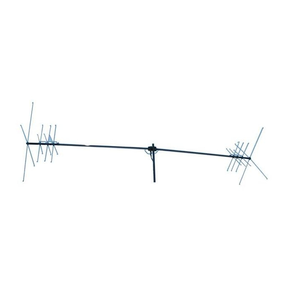
MFJ-1775 Rotatable Mini-Dipole
As you unpack your antenna you should find the parts in the following list.
Part Description
Balun
6-32 x 3/8" screw
¼-20 x 1-3/4 bolt
6-32 kep nut
10-32 hex nut
¼-20 hex nut
#10 lock washer
¼ split lock washer
Hose clamp (#16)
16" Threaded Rod (2M stub)
55" Threaded Rod (6M stub)
640 U-bolt Set
1/8" Plastic Spoke Caps
Aluminum "L" Stabilizer Bracket
Fiberglass Stabilizer Insulator
Aluminum Stub Channel Bracket
1 x 12" Fiberglass Rod
1-1/8 x 60" AL Tube
30" LONG Spokes
26" MEDIUM Spokes
12" SHORT Spokes
Loading Coil Assembly
For installation, you will need some items not supplied with the antenna installation kit:
•
A 6'-8' rigid mast or other mounting pipe between 1" and 1.5" outside diameter. (suitable materials
include TV mast sections, galvanized iron pipe, or heavy duty rigid conduit.)
•
Quality low-loss 50-Ohm coax with a PL-259 from antenna to transmitter.
An Antenna Analyzer (MFJ-259B or similar), or SWR meter and transceiver
Autoryzowany Przedstawiciel MFJ w Polsce:
MFJ-1775 PARTS LIST
INRADIO
ABEL & PRO-FIT Centrum Radiokomunikacji
ul. Puszkina 80
92-516 £ódŸ
tel.
(+42) 649 28 28
fax:
e-mail:
biuro@inRADIO.pl
internet:
www.inRADIO.pl
QTY
MFJ Part No.
1
80-1775-10
80
656-0375S
2
662-1760S-HH
80
705-0632S
10
705-1032S
4
705-2520S
5
711-1037S-EX
2
711-2537S-SL
8
745-3116S
2
758-8252
2
758-8253
2
758-9200
35
765-1002
4
805-1796-7
4
807-1796-6
4
808-1796-5
1
808-1775-12
2
810-1796-2
4
810-1796-3C
8
810-1796-5C
24
810-1796-6C
2
811-1796-1C1
Poland
(+42) 677 04 71
1
Instruction Manual
Advertisement
Table of Contents

Related Manuals for MFJ MFJ-1775


Summary of Contents for MFJ MFJ-1775
- Page 1 TV mast sections, galvanized iron pipe, or heavy duty rigid conduit.) • Quality low-loss 50-Ohm coax with a PL-259 from antenna to transmitter. An Antenna Analyzer (MFJ-259B or similar), or SWR meter and transceiver Autoryzowany Przedstawiciel MFJ w Polsce: INRADIO ABEL &...
-
Page 2: Specifications
If necessary, it can even be mounted inside an attic! The MFJ-1775 is inconspicuous and low profile -- not much bigger than a TV antenna, and can easily be turned by a lightweight TV rotator such as the Hy-Gain AR-35. -
Page 3: Choosing A Location For The Antenna
1-1/2" OD. The use of soft or thin wall masts is not recommended Portable Operation The MFJ-1775 may be disassembled as necessary for transporting to a temporary location. Ideally, just remove the two HF loading coil assemblies leaving the two main elements and 2- & 6-meter stub assemblies intact. -
Page 4: Tools And Time Required For Assembly
MFJ-1775 Rotatable Mini-Dipole Instruction Manual TOOLS AND TIME REQUIRED FOR ASSEMBLY The estimated assembly time is two hours. Antenna assembly requires the following hand tools • #2 Phillips screwdriver • 5/16" nut driver for #6 nuts and hose clamps. •... - Page 5 MFJ-1775 Rotatable Mini-Dipole Instruction Manual Step-By-Step Procedure 1) Set up saw horses or other stable supports (plastic trash cans, chairs, folding tables, etc.) to support the antenna during assembly. 2) Prepare a temporary 6-8’ ground-level mounting mast for easy initial testing and adjustment.
- Page 6 MFJ-1775 Rotatable Mini-Dipole Instruction Manual 7) Slide the 1-1/8 x 60” aluminum radiator tubes over the center insulator/balun assembly with the slot on each aluminum tube on the topside of the fiberglass rod/balun assembly. Insert the ¼-20 bolts through the aluminum tube/fiberglass assembly and through the balun lugs. Add the ¼-20 split lock-washers and nuts and tighten securely.
- Page 7 MFJ-1775 Rotatable Mini-Dipole Instruction Manual 11) Install the 6-32 screws in all rings of both loading coil assemblies, loosely holding them in place with their associated nuts. Position the screws so the threaded ends of the screws are pointed outward towards the two ends of each loading coil assembly as shown in Figure 5.
- Page 8 The MFJ-1775 covers wider frequency ranges on the higher bands, and narrower segments on the lower frequency bands. The 40 meter band has the narrowest range of operation (approximately 40 KHz) and is the most sensitive to adjustments.
-
Page 9: Tuning The Antenna
MFJ-1775 Rotatable Mini-Dipole Instruction Manual raised to the final height. However, when the plastic end caps are installed on the ends of the spokes, the resonant frequency on all bands is lowered 30-50 kHz Tuning the Antenna 1) Measure and record the frequency of lowest SWR for each band. The lowest SWR should be at or below the bottom end of each HF band. - Page 10 MFJ-1775 Rotatable Mini-Dipole Instruction Manual 20 M: 1" trimmed off a pair of spokes equals approximately 100 KHz 15 M: 1" trimmed off a pair of spokes equals approximately 175 KHz 10 M: 1" trimmed off a pair of spokes equals approximately 250 KHz Note: Typical final spoke lengths for the low end of each HF band are shown in the table on the next page.
-
Page 11: Grounding Considerations
MFJ-1775 Rotatable Mini-Dipole Instruction Manual TYPICAL FINAL SPOKE LENGTHS FOR HF CW BAND OPERATION • 40 Meters: 31-1/4” (full length) for two spokes on one loading coil only. 24-1/2” length for the remaining six 40 meter spokes. • 20 Meters: 12-1/4” length for all eight spokes. -
Page 12: Technical Assistance
MFJ Technical Service at 662-323-0549 or the MFJ Factory at 662-323-5869. You will be best helped if you have your unit, manual and all information on your station handy so you can answer any questions the technicians may ask.
Need help?
Do you have a question about the MFJ-1775 and is the answer not in the manual?
Questions and answers