Table of Contents
Advertisement
Quick Links
SK6288U3KOC
Color Line Scan Camera
3x 2096 pixels, 14 µm x 14 µm, 60 / 30 MHz pixel frequency
Instruction Manual
02.2016
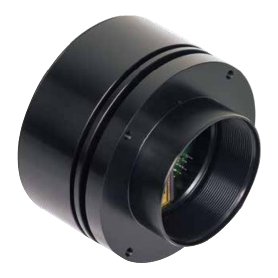
Sample Configuration
1
CCD line scan camera
SK6288U3KOC
mounted with
2
Mounting bracket SK5105
3
Clamping claws SK5102
4
Photo lens SK1.4/50-40
(integrated focus/aperture adjustment)
Read the manual carefully before the initial start-up. For the contents table, refer to page 3.
The right to change the described specifications is retained as the products undergo continuous cycles of improvement.
Kieler Str. 212, 22525 Hamburg, Germany
Tel: +49 40 85 39 97- 0
Fax: +49 40 85 39 97-79
•
•
USB
• Robust cable connections
• Hot-pluggable
• Perfect for movable setups
3
1
2
info@SuKHamburg.de
•
3.0
4
www.SuKHamburg.de
•
Advertisement
Table of Contents

Subscribe to Our Youtube Channel
Related Manuals for Schäfter+Kirchhoff SK6288U3KOC


Summary of Contents for Schäfter+Kirchhoff SK6288U3KOC
- Page 1 SK6288U3KOC • Robust cable connections Color Line Scan Camera • Hot-pluggable • Perfect for movable setups 3x 2096 pixels, 14 µm x 14 µm, 60 / 30 MHz pixel frequency Instruction Manual 02.2016 Sample Configuration CCD line scan camera SK6288U3KOC...
-
Page 2: How To Use This Instruction Manual
According to the application, laser or high power LED light sources might be used. These can affect your eyesight temporarily or even cause permanent da- mage to the eyes or skin. Do not look directly into the light beam! © 2016 SK6288U3KOC Instruction Manual (02.2016) Schäfter + Kirchhoff GmbH • Hamburg... -
Page 3: Table Of Contents
1.1 Intended Purpose and Overview ....................4 1.2 System Setup at a Glance ......................4 1.3 Computer System Requirements ....................5 1.4 SK6288U3KOC Line Scan Camera - Specifications ..............5 2 Installation and Setup ....................6 2.1 Mechanical Installation: Mounting Options and Dimensions ............. 6 2.2 Electrical Installation: Connections and I/O Signals .............. -
Page 4: Introduction
SK91USB3-WIN CD then the and scientific environments. The SK6288U3KOC is highly camera can be parameterized. The parameters, such as portable and the robustly attached dedicated connections... -
Page 5: Computer System Requirements
CD/DVD drive for software installation • USB 3.0 interface. With a USB 2.0 interface, there are limitations, see footer. • High-performance video card, PCIe bus 1.4 SK6288U3KOC Line Scan Camera - Specifications Sensor category CCD Color Sensor Sensor type KLI2113 Pixel number... -
Page 6: Installation And Setup
Set of 4 pcs. clamping claws incl. screws Hex socket head screw DIN 912–M3 x 12 Mounting system SK5105-2 for cameras with a tube extension > 52 mm 31.5 25 10 Ø4.3 © 2016 SK6288U3KOC Instruction Manual (02.2016) Schäfter + Kirchhoff GmbH • Hamburg... -
Page 7: Electrical Installation: Connections And I/O Signals
2.2 Electrical Installation: Connections and I/O Signals • The USB 3.0 interface provides data transfer, camera control and power supply capabilities to the SK6288U3KOC line scan camera. If you want to operate the camera in Free Run (SK Mode 0) trigger mode the USB 3.0 cable is the only connection you have to make. -
Page 8: Usb3 Connections And Sklinescan Software Installation
Quit the SkLineScan startup dialog box. • Select "OK" in the SkLineScan start-up dialog. The Signal Window showing the current brightness versus the pixel number indicates the correct installation. © 2016 SK6288U3KOC Instruction Manual (02.2016) Schäfter + Kirchhoff GmbH • Hamburg... - Page 9 © 2016 SK6288U3KOC Instruction Manual (02.2016) Schäfter + Kirchhoff GmbH • Hamburg...
-
Page 10: Camera Control And Performing A Scan
, and the index order corresponds with the individual MAC addresses of the cameras. If the SK6288U3KOC camera is identified correctly, confirm with "OK". The "Signal window" graphicaly showing the intensity signals of the sensor pixels (oscil- loscope display) will open. It is responsive in real-time... -
Page 11: Basic Visualization Of The Sensor Output
Line scan in Signal Split signal window. The upper frame shows a magnified section of the lower frame. © 2016 SK6288U3KOC Instruction Manual (02.2016) Schäfter + Kirchhoff GmbH • Hamburg... -
Page 12: Adjustments For Optimum Scan Results
• Dark-bright transitions with steep edges • Signal peaks are blurred • Large modulation in the signal peaks • High-frequency gray values with low • High-frequency gray value variations modulation © 2016 SK6288U3KOC Instruction Manual (02.2016) Schäfter + Kirchhoff GmbH • Hamburg... -
Page 13: Sensor Alignment
Gain slider 1. Adjust channel 1 zero level and minimize diffe- rence between channels using Offset slider Offset and gain adjustment for more than one gain/offset channel © 2016 SK6288U3KOC Instruction Manual (02.2016) Schäfter + Kirchhoff GmbH • Hamburg... -
Page 14: White Balance And Shading Correction
Open the "Gain/Offset Control" dialog. Use the gain sliders to adjust all three curves to the same level. Some camera models provide two gain/offset channels - thus two sliders - per color. "Gain/Offset Control" Dialog © 2016 SK6288U3KOC Instruction Manual (02.2016) Schäfter + Kirchhoff GmbH • Hamburg... - Page 15 Color line signal with the Red signal adjusted to that of the Blue channel; the Green channel is still separate Color line signal with balanced RGB curves © 2016 SK6288U3KOC Instruction Manual (02.2016) Schäfter + Kirchhoff GmbH • Hamburg...
- Page 16 Click on Save SCM to Flash to save the SCM power-up. reference signal in the flash memory of the camera Color line signal with separated RGB curves after Gain Adjustment and Shading Correction © 2016 SK6288U3KOC Instruction Manual (02.2016) Schäfter + Kirchhoff GmbH • Hamburg...
-
Page 17: Integration Time
'OK' stores the integration time values and closes the 95% of the available scale. dialog. • For synchronization settings, see section Synchro- nization of the Imaging Procedure and the Object Scan Velocity, p. 18. © 2016 SK6288U3KOC Instruction Manual (02.2016) Schäfter + Kirchhoff GmbH • Hamburg... -
Page 18: Synchronization Of The Imaging Procedure And The Object Scan Velocity
Pixel width = 14 µm 200 mm/s · (29.3 mm / 50 mm) Object scan velocity = 200 mm/s 14 µm = 29.3 mm = 50 mm 8.4 kHz © 2016 SK6288U3KOC Instruction Manual (02.2016) Schäfter + Kirchhoff GmbH • Hamburg... -
Page 19: Synchronization Modes
Each single line scan is triggered by the falling edge of a TTL signal supplied to LINE SYNC A input. The SK6288U3KOC line scan camera facilitates advanced synchronization control by a second trigger input LINE SYNC B. For a detailed description, see 4.2 Advanced Synchronization Control, p. 24... -
Page 20: Rgb Sensors: 2D Imaging And Pixel Allocation
RGB Sensors: 2D Imaging and Pixel Allocation The three lines of the implemented triple line sensor are The Camera SK6288U3KOC outputs the blue (B), sensitive for the primary colors blue (B), green (G) and green (G) and red (R)-information se quentially in one red (R). - Page 21 © 2016 SK6288U3KOC Instruction Manual (02.2016) Schäfter + Kirchhoff GmbH • Hamburg...
-
Page 22: Advanced Sklinescan Software Functions
The parameter settings are stored in the non-volatile flash memory of the camera and are available after a rapid start-up, even after a complete shut down or loss of power. Gain/Offset Control dialog: Camera Control input and output in the right section © 2016 SK6288U3KOC Instruction Manual (02.2016) Schäfter + Kirchhoff GmbH • Hamburg... -
Page 23: Set Commands
COG (coupling of gain1-gain3) = 0 ... 255 RESET<CR> reset Memory to manufacturer default xxxx = 4 digits integer value as ASCII yyyyy = 5 digits integer value as ASCII © 2016 SK6288U3KOC Instruction Manual (02.2016) Schäfter + Kirchhoff GmbH • Hamburg... -
Page 24: Advanced Synchronization Control
D6 = LINE SYNC A xxxxxx11 internal line counter (bit 7 ... 0) D5 = LINE SYNC B D4 ... D0 = line counter (bit 12 ... 8) © 2016 SK6288U3KOC Instruction Manual (02.2016) Schäfter + Kirchhoff GmbH • Hamburg... -
Page 25: Example Timing Diagrams Of Advanced Synchronization Control
'1110 0xxx'b • Trigger on 4 edges of SyncA and SyncB • direction detection = on • hysteresis = 4 Sync Control Register: '1110 1xxx'b machine holdup oscillation © 2016 SK6288U3KOC Instruction Manual (02.2016) Schäfter + Kirchhoff GmbH • Hamburg... -
Page 26: Sensor Information
5 Sensor Information 5 Sensor Information Manufacturer: Eastman Kodak Company Type: KLI2113 Data source: Kodak Digital Science KLI-2113 Image Sensor, Technical Data Revision 4 Single Channel Schematic Package Configuration © 2016 SK6288U3KOC Instruction Manual (02.2016) Schäfter + Kirchhoff GmbH • Hamburg... - Page 27 5 Sensor Information Typical Responsivity Defect Classification Test conditions: T = 25°C, f = 2 MHz, tint = 1.066 ms © 2016 SK6288U3KOC Instruction Manual (02.2016) Schäfter + Kirchhoff GmbH • Hamburg...
- Page 28 5 Sensor Information Electro-optical Characteristics © 2016 SK6288U3KOC Instruction Manual (02.2016) Schäfter + Kirchhoff GmbH • Hamburg...
- Page 29 © 2016 SK6288U3KOC Instruction Manual (02.2016) Schäfter + Kirchhoff GmbH • Hamburg...
-
Page 30: Glossary
83 kHz. During a scanning run, the effective resolution perpendi- cular to the sensor orientation is determined by the velocity of the scan and by the line frequency © 2016 SK6288U3KOC Instruction Manual (02.2016) Schäfter + Kirchhoff GmbH • Hamburg... -
Page 31: Ce-Conformity
Date of document publication: 10.02.2016 Schäfter+Kirchhoff GmbH Tel.: +49 40 853 997-0 Kieler Straße 212 Fax: +49 40 853 997-10 22525 Hamburg Email: info@SuKHamburg.de Germany Internet: www.SuKHamburg.com © 2016 SK6288U3KOC Instruction Manual (02.2016) Schäfter + Kirchhoff GmbH • Hamburg... -
Page 32: Accessories And Spare Parts
Accessories and Spare Parts USB 3.0 cable SK9020.x External synchronization cable SK9026... Camera connector: USB 3.0 plug, type micro-B, with safety lock for line scan cameras with USB 3.0 interface. screws Shielded cable with Hirose plug HR10A, female 6 pin (camera PC connector: USB 3.0 plug, type A (also fits into a USB 2.0 side), and Phoenix 4 pin connector incl.
Need help?
Do you have a question about the SK6288U3KOC and is the answer not in the manual?
Questions and answers