
Related Manuals for Magnadyne M9900-1


Summary of Contents for Magnadyne M9900-1
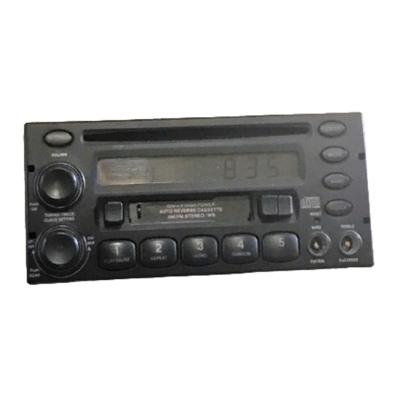
- Page 1 Installation and Operations Manual M9900-1 AM / FM / WB / AUX / CD / CD Changer Controller and Cassette Stereo Receiver...
- Page 2 Introduction Your new in-dash entertainment system has been designed for many years of listening pleasure. Take a moment to read through this manual and become familiar with the operations and features of this out- standing product. It is advisable to keep this manual in your vehicle ready for reference. We hope the experience with your new mobile entertainment system is a pleasurable one.
- Page 3 Location and Function of Controls at a Glance (Continued) 8. Recall Button #5: Press when programming a radio station into memory #5 (CH5). Press when recall- ing memorized radio station #5. Press to play the disc that follows the one that is currently playing in the optional CD changer.
-
Page 4: Listening To The Radio
Listening to the Radio 1. Push the “LEVEL” knob (2) once to turn the unit on. (Figure A) 2. Press the “BAND” button (12) to select a radio band: FM1, FM2, FM3, AM1 or AM2. 3. To manually tune in a radio station, rotate the “Tuning”... -
Page 5: Cassette Tape Operation
Weather Band Radio Operation 1. Press the “W.BAND” button (9) to activate the weather band radio. (The weather band radio will then take priority over the AM/FM Radio or CD). The weather band radio will search for the strongest radio signal in your area (Figure D). 2. - Page 6 CD’s in the CD chang- er. If a CD is not in a tray in the changer, the M9900-1 will continue to scroll through the Figure L (CD Changer Control Display) trays until one is found.
-
Page 7: Auxiliary Input
1. Press the “MODE” (13) button until the display reads “AUX” which indicates that the auxiliary unit is playing through the M9900-1 (Figure M). 2. All tonal features (Volume, Bass, Treble, Balance and Fader) are active when the auxiliary source is playing. -
Page 8: Setting The Clock
Setting the Clock Setting the Clock: To set the clock perform the following procedure: 1. Press the “Level” knob (2) to turn the unit on. 2. Press and hold the “Clock” button (11) (Figure Q) until the display begins to flash (Figure R). 3. -
Page 9: Installation Procedure
Installation Procedure Step 1: White Wire: Connect this wire to the Left Front The radio chassis is designed to be “Sleeve Speaker (+) positive terminal or wire. Mounted” through a opening in the dashboard panel. The required opening size is 182mm (7-3/16") x White Wire with Black Stripe: Connect this wire to the 84mm (3-5/16"). -
Page 10: Installation
Installation Sheet Metal Screw Washer Metal Strap Dashboard Mounting Sleeve Speaker Connection Right Right Front Speaker Rear Speaker Purple Wire: Rear Right Speaker (+) Purple/Black Wire: Rear Right Speaker (-) Gray/Black Wire: Front Right Speaker (-) Gray Wire: Front Right Speaker (+) Green Wire: Rear Left Speaker (+) Green/Black Wire: Rear Left Speaker (-) White/Black Wire: Front Left Speaker (-) -
Page 11: Auxiliary Connection
Auxiliary Connection M9900-1 Red (Right) White (Left) Video Game Audio Out from VCR / TV / Video Game or Satellite Receiver Satellite Receiver CD Changer Connection CD Changer M9900-1 Male/Male (Supplied with CD Changer) Black... -
Page 12: Warranty
Warranty ONE (1) YEAR LIMITED WARRANTY Magnadyne Corporation or its authorized agents will within one year from the date of sale to you, repair, replace or refund the retail sales price of said product or any part thereof, at the...
Need help?
Do you have a question about the M9900-1 and is the answer not in the manual?
Questions and answers