
Related Manuals for Global Lift Proformance Series


Summary of Contents for Global Lift Proformance Series
- Page 1 GLOBAL LIFT CORP Owner’s Manual Proformance Series 684 N Port Crescent Rd Suite C Bad Axe, MI 48413 Toll Free: 866-712-0606 Fax: 989-269-5902 www.globalliftcorp.com Page | 1...
- Page 2 SUPERIOR AND PROFORMANCE SERIES POOL LIFTS TABLE OF CONTENTS INTRODUCTION PAGE – 3 ADA GUIDELINES FOR PLACEMENT PAGE – 4 24 VOLT BATTERY SYSTEM/WITH CONTROLS PAGE – 5 SUPERIOR SERIES OPERATING INSTRUCTIONS PAGE – 6 UNIT MAINTENANCE AND CARE PAGE – 7 TROUBLESHOOTING PAGE –...
- Page 3 Your Number One Choice for Commercial Pool Access Equipment Global Lift Corp. is located in Mid Michigan, Global Lift Corp. prides itself in manufacturing top of line quality aquatic access equipment. Global Lift Corp.'s key staff has a century of combined industry experience and we take pride in each and every product that we build.
- Page 4 ADA GUIDELINES FOR POOL LIFT PLACEMENT 1. Pool Lift Location. Pool lifts shall be located where the water level does not exceed 48 inches (1220 mm). 2. Seat Location. In the raised position, the centerline of the seat shall be located over the deck and 16 inches (405 mm) minimum from the edge of the pool.
- Page 5 24 VOLT BATTERY SYSTEMS WITH CONTROLS All of Global Lift Corp’s Superior/Proformance Series Lifts are equipped with a sealed 24 volt battery that is rechargeable. Along with a charging unit, hand held controller and control compartment. The 24 volt battery mounts into the control compartment and the battery simply snaps in.
- Page 6 PERFORMANCE SERIES POOL LIFT OPERATING INSTRUCTIONS Prior to using the Proformance Series Pool Lift perform a test run of the lift empty. Once that is completed and the lift is back to original position, make sure that the arm lifts...
-
Page 7: Maintenance
Maintenance Regular servicing will help prolong the life of your lift. Routine maintenance and cleaning is very important. The following is a routine maintenance you should follow. Daily Check and charge battery if needed Test for normal operations Inspect your lift Clean and dry the lift and seat with clean water Cover lift after use Weekly... -
Page 8: Troubleshooting Guide
TROUBLESHOOTING GUIDE Before any troubleshooting commences make sure the battery has a full charge! (1) Does the lift raise or lower (a) Check to ensure the red button on the top is turned clockwise and up. (b) Check the battery connection and reconnect (c) Ensure that both the handset and actuator plugs are fully inserted (d) Check the cables for damage (e) Check to see if the battery has 24+ volts using a multimeter or volt... - Page 9 Global Lift Corp Warranty Information The Superior series lift has a 5 year structural limited warranty. Global Lift Corp warrants to the original retail end user only products manufactured by Global Lift Corp, when properly installed in accordance to the assembly and installation instructions, and when the equipment is properly used and maintained, to be free from material defects and workmanship as stated below: ...
- Page 10 Global Lift Corp’s decision regarding the claim. If the request made by Global Lift Corp for the product to be returned to its factory or distributor of choice for inspection and/or repair, purchaser will be liable for “Freight Prepaid”. Global Lift Corp at...
- Page 11 Global Lift Corporation or directly to Global Lift Corporation. All RGA (Return Goods Authorization) documents shall be requested by and issued only to the distributor which originated the sale or directly to Global Lift Corporation. Global Lift Corporation shall determine warranty coverage validation and replacement parts or repair, which were directed to the distributor which originated the sale or that are initiated directly with Global Lift Corporation.
- Page 12 I have read and I accept the warranty terms. Signature: ______________________________________ Date: ______________ This card must be completed and returned to Global Lift Corp within 30 days of purchase date to assure coverage. Please mail to: Global Lift Corp, 684 N Port Crescent Suite C, Bad Axe, MI 48413...
- Page 13 PERFORMANCE SERIES LIFT NEW CONSTRUCTION & SAW CUT SLEEVE ANCHORING METHOD INSTALLATION MANUAL Performance New Construction/Saw FEB 2015 Cut Anchor...
-
Page 14: Parts List
PERFORMANCE SERIES SLEEVE ANCHORING SYSTEM INSTALLATION PARTS LIST 1 - Anchor Sleeve w/ Base 1 - Binding screw 1 - Plastic Cap Performance New Construction/Saw FEB 2015 Cut Anchor... - Page 15 ANCHORING SLEEVE, BASE PLATE & BINDING SCREW Performance Series Performance New Construction/Saw FEB 2015 Cut Anchor...
- Page 16 ADA GUIDELINES FOR POOL LIFT PLACEMENT •Pool Lift Location. Pool lifts shall be located where the water level does not exceed 48 inches (1220 mm). Seat Location. In the raised position, the centerline of the seat shall be located over the deck and 16 inches (405 mm) minimum from the edge of the pool.
- Page 17 PERFORMANCE SERIES – SLEEVE ANCHORING SYSTEM Water Pool Wall 12” to 17” Distance From Water’s Edge (front edge of anchor sleeve) Actual application 3’ Overview Anchor Sleeve Section Detail 3’ 3’ Anchor Sleeve Cold Pin 6” Cold Pin Concrete Concrete Binding Screw COMPACT SAND Front of Anchor Sleeve must be 12”...
- Page 18 Step 1: Determine the location for installation (Make sure all ADA requirements are met). ***NOTE: The installation of Global Lift Corp’s anchor system’s are a guideline of minimum requirements. In some states or municipalities they may require additional steps due to their local codes or ordinances.***...
- Page 19 Step 5: Place the Anchor Sleeve in the cut out area, make sure that the front of the Anchor Sleeve is 12” to 17” from the water’s edge. (refer to overview) A key element is to make sure that the Anchor Sleeve is level and square with the pool so that your Superior Series Lift sits properly on the deck.
- Page 20 PERFORMANCE SERIES LIFT RETRO-FIT SLEEVE ANCHORING METHOD INSTALLATION MANUAL S & P Retro Fit Sleeve Anchoring Method...
-
Page 21: Packing List
RETRO-FIT SLEEVE ANCHORING SYSTEM PERFORMANCE SERIES LIFT PACKING LIST • 1 – Anchor Sleeve w/ Base • 1 – Binding Screw • 1 – Plastic Cap S & P Retro Fit Sleeve Anchoring Method... - Page 22 ADA GUIDELINES FOR POOL LIFT PLACEMENT •Pool Lift Location. Pool lifts shall be located where the water level does not exceed 48 inches (1220 mm). Seat Location. In the raised position, the centerline of the seat shall be located over the deck and 16 inches (405 mm) minimum from the edge of the pool.
- Page 23 NOTE: From the water’s edge to the front end of the Anchor sleeve must 12” to 17”. See picture B ***NOTE: The installation of Global Lift Corp’s anchor system’s are a guideline of minimum requirements. In some states or municipalities they may require additional steps due to their local codes or ordinances.***...
- Page 24 Front edge of anchor sleeve Measure Distance to make Sure It’s 12” to 17” to the water’s edge Picture B Picture A Step 2: You will need a 5” diameter core drilling bit. • Make sure you have accurately marked your hole location to be drilled. After drilling your hole (picture A), it must be 6”...
- Page 25 STEP 3 : Cementing the anchor sleeve in the concrete. Make sure your anchor is level and Square. • You will need 10 lbs of Quick dry Anchoring Cement (Commercial Grade Quikrete Exterior to complete the installation. You can purchase at any hardware Use Anchoring Cement) store in your area.
- Page 26 Fixed Anchor Performance Series Once you have completed the installation of your lift, locate the 3/8 bolt and secure it in the pre-drilled hole inside the anchor sleeve and tighten. Your lift is now ready to be used.
- Page 27 Optional Fixed Drop In Anchor Instructions for Performance Series Pre-drilled hole on the base of S-350 & P-375 Lift After you have installed your square anchor, You are ready to install the optional fixed drop in anchor. Position the lift into square anchor. Locate the pre-drilled hole on the base of the lift.
- Page 28 GLOBAL LIFT CORP CUSTOM SEAT INSTALLATION MANUAL C, P & S Series Lifts...
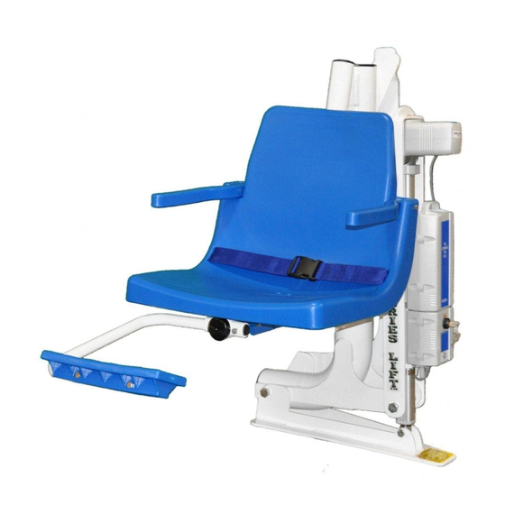
- Page 29 GLOBAL LIFT CORP CUSTOM SEAT INSTALLATION MANUAL PARTS LIST 1 - Custom Seat 1 - Foot Rest 2 – Arm Rests 1 - Seat Belt & Buckle 1 – ½” x 2 3/4” Securing Bolt ...
-
Page 30: Installation Steps
INSTALLATION STEPS Picture A Step 1: Unpack your custom seat (picture A). Loose Items will consist of: • Foot Rest and Tube • ½” x 3” Bolt w/ lock nut • 5/16” x 2 ¾” Bolt with Lock nut... - Page 31 INSTALLATION STEPS Picture A Picture B Step 2: Align your custom seat (Picture A), slide the lower seat tube into the upper Seat tube. Step 3: Once you have the seat in place, take your ½” x 3” bolt and slide it through the pre-drilled Holes (Picture B).
- Page 32 INSTALLATION STEPS Step 4: Locate the 5/16 x 3” securing bolt (supplied), insert the bolt through the pre-drilled Seat and tube holes (As shown Above). Once you have the bolt inserted, secure the installation With the lock nut that is provided and tighten down.
- Page 33 In picture B, locate the 5/16” x 2” bolt and insert into the pre-drilled holes to secure the foot rest to the lift. Place the lock nut on the bolt and tighten down. Once that is complete, you are ready to enjoy your Global Lift Corp pool lift.
Need help?
Do you have a question about the Proformance Series and is the answer not in the manual?
Questions and answers