
Subscribe to Our Youtube Channel
Related Manuals for Rinnai DO-SC18Z91


Summary of Contents for Rinnai DO-SC18Z91
- Page 1 Models: DO-SC18Z91 DI-XU18Z DO-SC22Z91 DI-XU22Z Brivis ICE – Fixed Speed Operation & Installation Manual...
- Page 2 This appliance must be installed in accordance with: • Manufacturer’s Installation Instructions • Current AS/NZS 3000, AS/NZS 1677.2, AS 4211.3, AS 4254, AS/NZS 5141, HB 276-2004 • Local Regulations and Municipal Building Codes including local OH&S requirements This appliance must be installed, maintained and removed by an Authorised Person.
-
Page 3: Table Of Contents
OPERATING TABLE OF CONTENTS Warnings and Important Information Operating Manual Introduction ............................... 7 1.2 Privacy Notification ............................ 7 How does your ICE system work? ......................7 Operating your Brivis Networker Wall Control (if applicable) ..............8 Operating the Fan Only ..........................9 Coded Messages ............................ - Page 4 This page is intentionally blank Brivis ICE Fixed Speed OM...
-
Page 5: Warnings And Important Information
WARNINGS AND IMPORTANT INFORMATION READ ALL INSTRUCTIONS BEFORE USING THE APPLIANCE. Always comply with the following precautions to avoid dangerous situations and to ensure optimum IMPORTANT performance. Failure to carefully read and follow all instructions in this manual can result in equipment malfunction, property damage, personal injury and/or death. - Page 6 OPERATION DO NOT let the air conditioner run for extended periods when the humidity is very high or when doors or WARNING windows are left open. As this may result in an excessive operational loading and lead to product failure. DO NOT cover or place articles on any part of this appliance.
-
Page 7: Operating Manual
1. OPERATING MANUAL INTRODUCTION Congratulations on your purchase of a Brivis ICE Add-On cooling split system. To achieve the performance and efficiency expected from your new ICE system, please ensure the Installer is a qualified tradesperson, that the Installer has commissioned the unit and instructed you on its operation. Please also take the time to read the contents of this manual, register your product warranty and retain this document for future reference. -
Page 8: Operating Your Brivis Networker Wall Control (If Applicable)
OPERATING YOUR BRIVIS NETWORKER WALL CONTROL (IF APPLICABLE) The Brivis Networker wall control operates the complete heating and cooling system, communicating key information and sensing the temperature. Table 1 details the functions and symbols of the networker control unit. The networker does not require batteries. If the networker display is blank, check that the 240V power supply and the thermostat cable are correctly connected. -
Page 9: Operating The Fan Only
Appliance Operating Symbols When the Networker is switched on certain operating symbols appear describing the operation of the air-conditioner appliance. • When the Networker switches ON to HEAT, a flame symbol will appear on the screen • When the Networker switches ON to COOL, a snowman symbol will appear on the screen •... -
Page 10: Coded Messages
CODED MESSAGES While the Networker is operating your system, it is also monitoring and controlling every aspect of the system’s performance. If anything unusual occurs, the Networker will display a message stating “Air-Conditioner Fault – R01 Code#??” for assistance call the number across the top of the screen. There are two parts to the message: the R01 number designates which appliance has the fault, and the “Code#??”... -
Page 11: Lock The Networker
LOCK THE NETWORKER To prevent unwanted adjustments to the cooler/heater settings, the networker can be locked with the use of a 4-digit PIN. In the case of dual networkers, locking one also locks the other, although the PIN must be set at the master networker. -
Page 12: Service & Maintenance
2. SERVICE & MAINTENANCE To ensure continuing high performance and to minimise the possibility of premature equipment failure, periodic maintenance must be performed on the air conditioning equipment. It is recommended the unit be maintained by a qualified person as follows: The minimum maintenance requirements for this equipment are as follows: Fortnightly •... -
Page 13: Product Registration
PRODUCT REGISTRATION If in Australia, to register your product warranty online please visit www.rinnai.com.au/support-resources/warranty- registration/ MAINTENANCE Return Air Filter Where fitted, the return air filter must be cleaned at least every two weeks during the heating season. A dirty air filter will reduce the efficiency, effectiveness and air quality of the system. -
Page 14: General User Guide
GENERAL USER GUIDE OPERATION AND MAINTENANCE Welcome to high efficiency year-round comfort. Congratulations on your excellent choice and sound investment in a Brivis Dual Comfort Home System. Please also take the time to read the contents of this Operating Manual, register your product warranty and retain this document for future reference. -
Page 15: Cooling Cycle
This System will automatically modulate the outdoor unit capacity in response to the demand of the conditioned space, to help ensure rapid cool down times, as well as providing more constant temperature control. Please refer to the Operating Instructions accompanying your Thermostat / Controller. COOLING CYCLE When operating in the COOL mode, your system will run until the indoor temperature is lowered to the level you have selected (within design conditions). -
Page 16: Care & Maintenance
CARE & MAINTENANCE CUSTOMER CARE PROGRAM Please ensure you register your product warranty on line at brivis.com.au. The Brivis Customer Care Program is designed to help you get the most out of your new system. Service and maintenance in accordance with the Service Maintenance Schedule on page 20 is essential in ensuring the prolonged useful life of your system, and help ensure it operates at optimum efficiency. -
Page 17: General Maintenance
Any unit repairs, maintenance and cleaning of the outdoor unit should be performed by an authorised dealer or licensed service provider. NOTE GENERAL MAINTENANCE Maintenance - For Prolonged Periods of Non Use If you plan not to use your air conditioner for an extended period of time, do the following. •... -
Page 18: Save A Service Call
service matters for these items. Whilst they are an integral part of your home comfort system, these non-Brivis items are not covered by your Brivis Product Warranty. Third party controls and zoning systems that interfere with the correct operation of your Brivis system, and any consequential damages to Brivis equipment as a result of such incorrect operation, will not be covered by Brivis Warranty. -
Page 19: When To Call For Service
The air conditioner does not generate Air is not circulating properly. Make sure that there are no curtains, cool air. blinds or furniture blocking the front of the air conditioner. The air filter is dirty. Clean the air filter once every 2 weeks. See “Cleaning Air Filter”... -
Page 20: Service Maintenance Schedule - Ducted Air Conditioning Systems
SERVICE MAINTENANCE SCHEDULE - DUCTED AIR CONDITIONING SYSTEMS Your Brivis Air Conditioning System should be maintained annually after the date of installation by a qualified licensed technician in accordance with the Schedule below. Failure to do so during the product warranty period may void your warranty. -
Page 21: Installation Record - Installer Details
INSTALLATION RECORD - INSTALLER DETAILS Company Name: ________________________________________________________________ Company Address: ________________________________________________________________ ________________________________________________________________ ________________________________________________________________ Telephone: ________________________________________________________________ Mobile Phone: ________________________________________________________________ Email: ________________________________________________________________ Certificate of Compliance / Certification No. ___________________________________________________ Authorised Persons - Licence No. ___________________________________________________ Installers Name: ________________________________________________________________ Installers Signature: ________________________________________________________________ Installation Date: ________________________________________________________________ INSTALLATION RECORD - SYSTEM DETAILS Model Number :... -
Page 22: Warranty
WARRANTY TERMS OF WARRANTY – AUSTRALIA Rinnai Australia Pty. Ltd. ABN 74 005 138 769, 100 Atlantic Drive, Keysborough VIC 3173. NOTICE TO CONSUMERS UNDER AUSTRALIAN CONSUMER LAW Our goods and services come with guarantees that cannot be excluded under the Australian Consumer Law. - Page 23 Normal Business Hours by an Authorised Service Representative. Repair by persons other than an Authorised Service Representatives may void the Warranty. 2.4 Alternatively to clause 2.3 above, Rinnai can at its discretion elect to pay you an amount equivalent to the cost of repairing or replacing the Product.
- Page 24 “7 Purchaser’s Responsibilities” on page 25; c) notifies Rinnai within 30 days of a defect occurring or, in the case of a latent defect, becoming apparent, that a claim is being made under this Warranty; and d) provides, in support of the claim made under this Warranty, a Proof of Purchase.
- Page 25 Rinnai to enquire about alternative arrangements. If you wish to make a warranty claim in respect of any fixed Product, please contact Rinnai on the details set out below to make arrangements for an Authorised Service Representative to inspect the product.
- Page 26 Warranty summary DEFINITIONS The terms listed below shall have the following meanings: “Authorised Service Agent” means an independent service contractor authorised by Rinnai or Rinnai service personnel. “Rinnai” means Rinnai New Zealand Ltd (Company Registration Number 94694) and any related company.
- Page 27 Hours by an Authorised Service Agent. Repair by persons other than an Authorised Service Agents may void the Warranty. 9.4 Alternatively, to clause 2.3 above, Rinnai can at its discretion elect to pay you an amount equivalent to the cost of repairing or replacing the Product.
- Page 28 “Purchaser’s Responsibilities” as per the owner’s manual; c) notifies Rinnai within 30 days of a defect occurring or, in the case of a latent defect, becoming apparent, that a claim is being made under this Warranty; and d) provides, in support of the claim made under this Warranty, a Proof of Purchase.
- Page 29 Product or any of its parts and/or servicing the Product, are expressly excluded. 12.4 Geographical Climate Zones – Rinnai New Zealand Ltd does not exclude this product from installation in the Cool climatic zone (see below reference map) but cannot guarantee appliance heating performance as per the published literature at temperatures below zero.
- Page 30 Rinnai to enquire about alternative arrangements. If you wish to make a warranty claim in respect of any fixed Product, please contact Rinnai on the details set out below to make arrangements for an Authorised Service Agent to inspect the product.
- Page 31 INSTALLATION TABLE OF CONTENTS 1. Introduction 1.1 Brivis ICE R410a Fixed Speed Range ....................33 1.2 Safety / Warnings ............................ 33 1.3 Codes / Regulations ..........................33 2. Components 2.1 Indoor Unit (Cooling Coil) ........................34 2.2 Starting Collars ............................34 2.3 P-Trap ..............................
-
Page 32: Introduction
For safety and warranty purposes, appliances that may be damaged or incorrect MUST NOT be installed or operated under any circumstances. Installation of damaged or incorrect appliances may contravene local government regulations. Rinnai disclaims any liability or responsibility whatsoever in relation to the installation or operation of damaged or incorrect appliances. -
Page 33: Brivis Ice R410A Fixed Speed Range
ICE Outdoor ICE Indoor Nominal Cooling Rated Cooling Recommended Brivis Gas Model Model Capacity (kW) Capacity (kW) Ducted Heater Model DO-SC18Z91 DI-XU18Z 18.2 Refer to latest Brivis Gas Ducted Heater Specifications for DO-SC22Z91 DI-XU22Z 22.2 Maximum Recommended Add-On Cooling Capacity Table 2. -
Page 34: Components
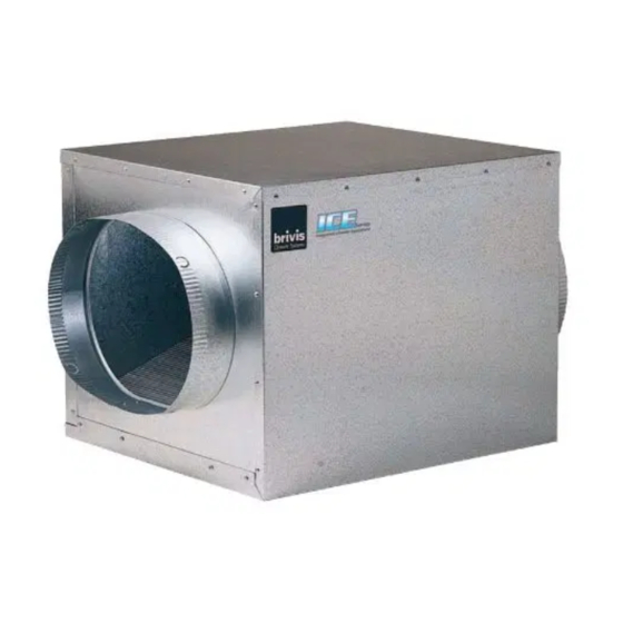
2. COMPONENTS INDOOR UNIT (COOLING COIL) Remove packaging from unit and any protective foam packing from coils and pipes. Indoor units are shipped with a holding charge of dry nitrogen. Check to confirm the holding charge. For lifting details refer to the General Arrangement drawings. -
Page 35: P-Trap
P-TRAP The indoor coil incorporates an evaporator drip tray and is supplied with a 20mm Female Pressure Pipe drain spigot, which is to be connected to the “P” trap (supplied). • Always install the “P” trap as close to the unit as possible. •... -
Page 36: Typical Installation
3. TYPICAL INSTALLATION Figure 6. Typical Indoor Installation A. Ensure 1m minimum, or preferably 2½ times the duct diameter, STRAIGHT duct length before any take-offs occur. Minimum B. Ensure 1m minimum STRAIGHT duct Minimum between the Gas Ducted Heater and ICE coil unit. -
Page 37: Indoor Coil Installation
4. INDOOR COIL INSTALLATION • Indoor coils are supplied with a nitrogen holding charge ranging from 400kPa to 700kPa • Connect a suitable pressure gauge to the indoor coil valve to ensure the internal pressure is at least 400kPa • If the measured pressure is less than 400kPa, check and if necessary repair any leaks found before proceeding •... -
Page 38: System And Ductwork Design
Figure 8. Indoor Service Clearances 600mm Access Panel 600mm Platform and Airflow Service Clearance Required SYSTEM AND DUCTWORK DESIGN Good duct design and sizing are essential to every Brivis ICE cooling system. Use the Brivis “SuperSizeGuide”, Technical Data Sheets, AS/NZS 5141 or HB276. In general: •... -
Page 39: General Arrangement Drawings
GENERAL ARRANGEMENT DRAWINGS Figure 9. Indoor Unit Dimensions DI-XU18Z 450mm Pop 400mm Pop Outlet Inlet 18” 16” Figure 10. Indoor Unit Dimensions DI-XU22Z 500mm Pop 450mm Pop Inlet Outlet 18” 20” Brivis ICE Fixed Speed OIM... -
Page 40: Outdoor Unit Installation
5. OUTDOOR UNIT INSTALLATION LOCATION • The unit must be installed in accordance with relevant authority requirements • The unit should not be accessible to general public • Do not install the unit where there is a possibility it will present a noise problem for either the home owner or neighbours, or exceed the noise guidelines as set down by local or state legislation or regulatory bodies •... - Page 41 There is no time delay built into the outdoor condensing unit to prevent compressor short cycling on rapid calls from the thermostat for cooling. Time delays providing this protection are built into the recommended Brivis Controllers. NOTE When adding Brivis ICE to a system where a non-Brivis heater is installed, it is the installer’s responsibility to ensure that some form of time delay or other protection is installed to prevent the compressor from short cycling.
-
Page 42: Wiring Diagrams
WIRING DIAGRAMS Figure 11. Typical Outdoor Unit Wiring Diagram (DO-SC22Z91 shown) NOTE: MAINS ISOLATOR SHORT CIRCUIT AND SHORT CIRCUIT PROTECTION BY OTHERS SWITCHBOARD LAYOUT OF OUTDOOR UNIT Compressor start signal 24VAC. The maximum allowable starts are 6 per hour. No internal compressor start limit timer is provided. This shall be incorporated into the thermostat. -
Page 43: Adaptive Zoning Options
ADAPTIVE ZONING OPTIONS StarPro SP6, SP5 and SP4 heaters can be configured for zoning and/or Add-On Refrigerative Air Conditioning. There are four 24 Vac relays on the heater’s control module, which can be configured to control up to four zone motors. - Page 44 Figure 13. Brivis ICE Add-On Schematic - Typical HEATER Heater Programmable 240V Control Active Thermostat Board Terminal Relay Block B063283 Brown Blue Fan speed terminal block White Relay Wires To Add-On Cooling Unit PCB Wires For connection refer to the installation manual Field Supplied Wires accompanying the Add-On cooling unit.
-
Page 45: General Arrangement Drawings & Clearance Requirements
GENERAL ARRANGEMENT DRAWINGS & CLEARANCE REQUIREMENTS Figure 14. Outdoor Unit: DO-SC18Z91 & DO-SC22Z91 (dimensions in mm) 1258 PLAN VIEW NOTE 6 NOTE 5 NOTE 3 NOTE 4 NOTE 2 FRONT SIDE NOTE: 1. Unit illustrated is a horizontal single stage outdoor unit 2. -
Page 46: Refrigeration Charge & Pipe-Work
6. REFRIGERATION CHARGE & PIPE-WORK • Both indoor and outdoor units come delivered under positive pressure • The outdoor unit is charged with sufficient R410a refrigerant for an interconnecting pipe run WARNING of 15m actual length • The indoor unit is pressurised with 400kPa to 700kPa dry nitrogen •... -
Page 47: Recommended Interconnecting Pipe Sizing
NOTE Therefore, two 12.7 to 9.52mm copper bushes are included (one with the indoor DI-XU18Z and one with the DO-SC18Z91 outdoor unit). For pipe work more than 10m equivalent length, a 12.7mm liquid line is needed. MAX VERTICAL PIPE RUN The height difference between indoor and outdoor units must not exceed 8 meters. -
Page 48: Charging The System
CHARGING THE SYSTEM Once all electrical connections are correctly made, the unit is ready to be commissioned. Start the system in cool mode and allow it to stabilise before checking liquid line sub-cooling and compressor suction superheat. Refer to Start Up and Commissioning procedures (Section 7). •... -
Page 49: Start-Up And Commissioning
7. START-UP AND COMMISSIONING • Ensure that a Return Air Filter is fitted prior to fan start up • Measure and record the system details as noted under PRELIMINARY SYSTEM INFORMATION and check all items as noted under PRE START-UP on the Commissioning Sheet provided •... -
Page 50: Sequence Of Operation
FAILURE TO COMPLETE PROPER START UP AND COMMISSIONING MAY VOID BRIVIS PRODUCT WARRANTY SEQUENCE OF OPERATION Check correct sequence of operation, then proceed to instruct customer on correct thermostat operation for refrigerated cooling. Refer to the thermostat operating instructions. . Ventilation Set the thermostat to the fan only mode. - Page 51 1020 1060 1100 1140 1180 1220 Dry Coil Wet Coil Table 8. Expanded Ratings (DO-SC18Z91 / DI-XU18Z) Based on 900 L/s Rated Airflow Indoor Unit Temperature Air Temperature Entering Dry Bulb Wet Bulb Dry Bulb Wet Bulb Dry Bulb Wet Bulb Outdoor Unit °C...
- Page 52 Figure 16. DO-SC18Z91 / DI-XU18Z Capacity / Airflow Chart Rated Air Flow Minimum Air Flow Table 9. Coil Static Pressure Drop - DI-XU18Z Airflow Dry Coil Wet Coil Brivis ICE Fixed Speed OIM...
-
Page 53: Technical Specifications
8. TECHNICAL SPECIFICATIONS Table 10. Technical Specification Data ICE Outdoor Unit UNIT DO-SC18Z91 DO-SC22Z91 Nominal Capacity Rated Capacity (AS 3823.3 - 2012) 18.2 22.2 Cooling Capacity Rated Input 5200 5840 AEER 3.50 3.80 Power Supply V-ph-Hz 415 -3 -50 415 -3 -50... -
Page 54: Commissioning
9. COMMISSIONING COMMISSIONING CHECK LIST Installer to please complete all sections of this form. SYSTEM INFORMATION ICE MODEL SERIAL No. (Outdoor Unit) (Outdoor Unit) ICE MODEL SERIAL No. (Indoor Unit) (Indoor Unit) HEATER MODEL HEATER SERIAL No. INSTALLED BY/ DATE PRE START-UP (Please tick boxes below as each item is completed). - Page 55 NOTES Brivis ICE Fixed Speed OIM...
-
Page 56: Contacts
Tel: 1300 555 545* Fax: 1300 555 655 Monday to Friday, 8.00 am to 5.00 pm EST. *Cost of a local call higher from mobile or public phones. For further information visit www.rinnai.com.au or email enquiry@rinnai.com.au innai New Zealand Ltd...
Need help?
Do you have a question about the DO-SC18Z91 and is the answer not in the manual?
Questions and answers