Table of Contents
Advertisement
Quick Links
Advertisement
Table of Contents

Related Manuals for MSI MS-9A79


Summary of Contents for MSI MS-9A79
- Page 1 MS-9A79 Industrial Data Machine...
-
Page 2: Revision History
Preface Copyright and Trademarks Notice Copyright © Micro-Star Int’l Co., Ltd. All rights reserved. The MSI logo used is a registered trademark of Micro-Star Int’l Co., Ltd. All other marks and names mentioned may be trademarks of their respective owners. No warranty as to accuracy or completeness is expressed or implied. -
Page 3: Safety Instructions
MS-9A79 Safety Instructions ■ Always read the safety instructions carefully. ■ Keep this User’s Manual for future reference. ■ Keep this equipment away from humidity. ■ Lay this equipment on a reliable flat surface before setting it up. ■ The openings on the enclosure are for air convection hence protects the equipment from overheating. -
Page 4: Chemical Substances Information
Chemical Substances Information In compliance with chemical substances regulations, such as the EU REACH Regulation (Regulation EC No. 1907/2006 of the European Parliament and the Council), MSI provides the information of chemical substances in products at: https://www.msi.com/html/popup/csr/evmtprtt_pcm.html Battery Information European Union: Batteries, battery packs, and accumulators should not be disposed of as unsorted household waste. -
Page 5: Ce Conformity
MSI will comply with the product take back requirements at the end of life of MSI-branded products that are sold into the EU. -
Page 6: Table Of Contents
Preface CONTENTS Copyright and Trademarks Notice ..............ii Revision History .................... ii Technical Support ..................ii Safety Instructions ..................iii Chemical Substances Information ............... iv Battery Information ..................iv CE Conformity ....................v FCC-A Radio Frequency Interference Statement ......... v WEEE Statement ..................v 1. - Page 7 MS-9A79 Power .......................3-17 Save & Exit ....................3-19 Appendix GPIO WDT BKL Programming ........A-1 Abstract ..................... A-2 General Purposed IO ................A-3 Watchdog Timer ..................A-4 LVDS Backlight Brightness Control ............A-5 SMBus Access ..................A-6...
-
Page 9: Overview
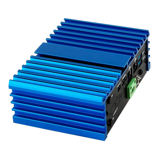
Overview Thank you for choosing the MS-9A79, an excellent industrial data machine from MSI. The MS-9A79’s wide heatsink fanless solution eliminates the noise and the risk of fan’s failure. Furthermore, it supports VESA wall-mount interface for various scenarios like digital signage, kiosk, industrial... -
Page 10: Package Contents
Overview Package Contents 1. MS-9A79 Industrial Data Machine 2. Power Adapter & Power Cord 3. Wall Mount Set 4. DIN Rail Mount Set 5. VESA Mount Set (Optional) 6. SATA Power & Signal Cable 7. Phoenix Plug-in Terminal Block 8. Jumper Caps 9. -
Page 11: System Overview
MS-9A79 System Overview System I/O & Controls... - Page 12 Overview WLAN Antenna Connector (Optional) This connector allows you to connect an external antenna for wireless LAN. Power Button Press the button to turn the system on or off. Extend Switch Connector This connector is provided for remote power button control. DIO Port This port is provided for the Digital Input/Output (DIO) peripheral module.
- Page 13 MS-9A79 RS232/422/485 Serial Port The serial port is a 16550A high speed communications port that sends/ receives 16 bytes FIFOs. It supports barcode scanners, barcode printers, bill printers, credit card machine, etc. SIGNAL DESCRIPTION NDCD Data Carrier Detect NSIN Signal In...
- Page 14 Overview LVDS Port (Optional) The LVDS (Low Voltage Differential Signal) connector provides a digital interface typically used with flat panels. DVI Port (Optional) Digital Visual Interface (DVI) is a video display interface developed by the Digital Display Working Group (DDWG). The digital interface is used to connect a video source, such as a video display controller, to a display device, such as a computer monitor.
- Page 15 MS-9A79 USB 3.0 Port The USB 3.0 port is backward-compatible with USB 2.0 devices and supports data transfer rate up to 5 Gbit/s (SuperSpeed). Grounding Point The Grounding Point is provided to connect a grounding wire.
-
Page 16: System Specifications
Overview System Specifications Processor ■ Intel Atom™ x5 E3940 Processor for WT SKU ® ■ Intel Celeron N3350 Processor for Non-WT SKU ® ® Memory ■ Onboard 4GB Single-Channel LPDDR4 Memory ■ 2133 MHz for E3940 SKU ■ 2400 MHz for N3350 SKU Network ■... - Page 17 MS-9A79 Expansion Slot ■ 1 * Mini-PCIe1 (Full-size, with Nano SIM-Holder) ■ 1 * Mini-PCIe2 (Half-size, with mSATA) Front Panel Input/Output ■ 2 * WLAN Antenna Connectors (Optional) ■ 1 * Power Button ■ 1 * Extend Switch Connector ■ 1 * DIO Port ■...
- Page 18 Overview Environment E3940 SKU N3350 SKU Environment Operating ■ -20 ~ 70°C (with WT SSD/ ■ -10 ~ 60°C (with SSD/ Temperature mSATA) mSATA, MS-99C0 LVDS to ■ -10 ~ 60°C (with MS-99C0 DVI-I converter board) LVDS to DVI-I converter board) Storage -40 ~ 80...
-
Page 19: Motherboard Jumpers
MS-9A79 Motherboard Jumpers Important Avoid adjusting jumpers when the system is on; it will damage the motherboard. JINVDD1 JVDD1 JCOMP1 JNVM2 JCMOS1 JNVM1 JDNX1 JTXE1 JAT1 1-11... - Page 20 Overview Clear CMOS Jumper: JCMOS1 Normal Clear CMOS (Default) AT/ATX Select Jumper: JAT1 ATX (Default) Serial Port Power Jumper: JCOMP1 +12V (Default) LVDS Power Jumper: JVDD1 (Default) LVDS Inverter Power Jumper: JINVDD1 (Default) 1-12...
- Page 21 MS-9A79 TXE F/W Jumper: JTXE1 Normal Disable (Default) DNX F/W Jumper: JDNX1 Do not force Force (Default) LAN NVM Jumpers: JNVM1, JNVM2 On: Enable security Off: Disable security and the INVM lock and the INVM lock (Default) (Non-secure mode) 1-13...
-
Page 22: System Dimensions
Overview System Dimensions 1-14... -
Page 23: Mounting Brackets
MS-9A79 Mounting Brackets 1-15... - Page 24 Overview 1-16...
-
Page 25: Getting Started
Getting Started This chapter provides you with the information on hardware setup procedures. While doing the installation, be careful in holding the components and follow the installation procedures. For some components, if you install in the wrong orientation, the components will not work properly. -
Page 26: Installation Tools
Getting Started Installation Tools A Phillips (crosshead) screwdriver and a flathead screwdriver, can be used to do most of the installation. Choose one with a magnetic head would be better. Pliers, can be used as an auxiliary tool to connect some connectors or cables. -
Page 27: System Cover
MS-9A79 System Cover 1. Place the system horizontally on a flat and steady surface. Locate and remove the screws that secure the system cover. 2. Lift the cover carefully upwards and remove it from the system. -
Page 28: Msata Card (Optional)
Getting Started mSATA Card (Optional) Important For Mini PCIe cards that draw power from the motherboard, make sure they operate at exactly the same voltage as the system power source. 1. Locate the half-size Mini PCIe slot. Remove the screw preinstalled on the motherboard. -
Page 29: Wifi Card (Optional)
MS-9A79 WiFi Card (Optional) Important For Mini PCIe cards that draw power from the motherboard, make sure they operate at exactly the same voltage as the system power source. 1. Find the antenna cable modules in the accessory box. 2. Assemble the antenna cables to the system front or rear panel as... - Page 30 Getting Started 3. Locate the Mini PCIe slot. Remove the Mini PCIe card screw preinstalled on the motherboard. 4. Insert the WiFi card into the slot at a 45-degree angle. 5. Push the card gently downwards and fasten it with the screw.
- Page 31 MS-9A79 6. Connect the antenna cables.
-
Page 32: Wifi Antenna (Optional)
Getting Started WiFi Antenna (Optional) 1. Find the WiFi antennas in the accessory box. Turn clockwise to lock the antennas and counterclockwise to unlock. 2. Adjust the direction of the antennas for better signal reception. -
Page 33: Lvds Cable (Optional)
MS-9A79 LVDS Cable (Optional) 1. Remove the screw and LVDS bracket with pliers. 2. Secure the LVDS cable to the system rear panel with two hexagonal screws. 3. Connect the LVDS cable to the LVDS connector on the motherboard. Make sure the LVDS cable is inserted in the right direction. -
Page 34: Lvds To Dvi-I Converter Board (Optional)
Getting Started LVDS to DVI-I Converter Board (Optional) 1. Remove the screw and LVDS bracket with pliers. 2. Secure the LVDS to DVI-I Converter Board to the system rear panel with two hexagonal screws. 3. Connect the Converter Board’s cable to the LVDS connector on the motherboard. -
Page 35: 2.5" Ssd/Hdd
MS-9A79 2.5” SSD/HDD 1. Loosen the screws from the system cover to release the hex nuts on the other side of the cover. 2. Remove the sticker film to uncover the thermal paste. 3. Place the SSD/HDD onto the system cover with screw holes aligned. - Page 36 Getting Started 5. Connect the SATA signal & power cable to the motherboard. 6. Connect the SATA signal & power cable to the SSD/HDD. 7. Align the notches and replace the system cover. 2-12...
- Page 37 MS-9A79 Fasten the screws to secure the system cover. 2-13...
-
Page 38: Wall Mount
Getting Started Wall Mount 1. Check the accessory box for the wall mount bracket modules. 2. Insert the rubber pads into the holes. 3. Insert the screws. 2-14... - Page 39 MS-9A79 4. Flip over the system and locate the bracket screw holes. 5. Place the brackets along the sides with screw holes aligned. 6. Fasten the screws to fix the wall mount brackets. 2-15...
-
Page 40: Din Rail Mount 1
Getting Started DIN Rail Mount 1 1. Check the accessory box for the DIN rails. 2. Put the DIN rails on the wall mount brackets with the hooks aligned. 2-16... - Page 41 MS-9A79 3. Insert screws through the wall mount brackets into the DIN rails and tighten until each DIN rail is secure. 2-17...
-
Page 42: Din Rail Mount 2 (Optional)
Getting Started DIN Rail Mount 2 (Optional) 1. Check the VESA mount plate for the DIN rail screw holes. 2. Put the DIN rails on the VESA mount plate with screw holes aligned. 3. Insert screws through the VESA mount plate into the DIN rails and tighten until each DIN rail is secure. - Page 43 MS-9A79 4. Install the wall mount brackets to the system. 5. Mount the VESA mount plate onto the system and tighten the thumbscrew of the VESA mount plate. 2-19...
-
Page 44: Vesa Mount (Optional)
Getting Started VESA Mount (Optional) 1. Locate the VESA mount screw holes on the intended device. 2. Fasten the VESA mount plate to the device with the supplied screws. 3. Install the wall mount brackets to the system. 2-20... - Page 45 MS-9A79 4. Mount the system onto the VESA mount plate. 5. Tighten the thumbscrew at the bottom of the VESA mount plate to secure the system. 2-21...
-
Page 47: Bios Setup
BIOS Setup This chapter provides information on the BIOS Setup program and allows users to configure the system for optimal use. Users may need to run the Setup program when: ■ An error message appears on the screen at system startup and requests users to run SETUP. -
Page 48: Entering Setup
BIOS Setup Entering Setup Power on the computer and the system will start POST (Power On Self Test) process. When the message below appears on the screen, press <DEL> or <F2> key to enter Setup. Press <DEL> or <F2> to enter SETUP If the message disappears before you respond and you still wish to enter Setup, restart the system by turning it OFF and On or pressing the RESET button. - Page 49 MS-9A79 Control Keys ← → Select Screen ↑ ↓ Select Item Enter Select Change Option General Help Previous Values Optimized Defaults Save & Reset Exit Getting Help After entering the Setup menu, the first menu you will see is the Main Menu.
-
Page 50: The Menu Bar
BIOS Setup The Menu Bar ▶ Main Use this menu for basic system configurations, such as time, date, etc. ▶ Advanced Use this menu to set up the items of special enhanced features. ▶ Boot Use this menu to specify the priority of boot devices. ▶... -
Page 51: Main
MS-9A79 Main ▶ System Date This setting allows you to set the system date. The date format is <Day>, <Month> <Date> <Year>. ▶ System Time This setting allows you to set the system time. The time format is <Hour> <Minute> <Second>. -
Page 52: Advanced
BIOS Setup Advanced ▶ Full Screen Logo Display This BIOS feature determines if the BIOS should hide the normal POST messages with the motherboard or system manufacturer’s full-screen logo. When it is enabled, the BIOS will display the full-screen logo during the boot-up sequence, hiding normal POST messages. - Page 53 MS-9A79 ▶ Super IO Configuration ▶ Serial Port 1, Serial Port 2 This setting enables/disables the specified serial port. ▶ Change Settings This setting is used to change the address & IRQ settings of the specified serial port. ▶ Mode Select Select an operation mode for the specified serial port.
- Page 54 BIOS Setup ▶ H/W Monitor These items display the current status of all monitored hardware devices/ components such as voltages, temperatures and all fans’ speeds. ▶ Thermal Shutdown This setting enables/disables the thermal shutdown function for system thermal protection. ▶ CPU Configuration ▶...
- Page 55 MS-9A79 ▶ EIST EIST (Enhanced Intel SpeedStep Technology) allows the system to dynamically adjust processor voltage and core frequency, which can result in decreased average power consumption and decreased average heat production. When disabled, the processor will return the actual maximum CPUID input value of the processor when queried.
- Page 56 BIOS Setup ▶ GPIO Group Configuration ▶ GPO0 ~ GPO7 These settings control the operation mode of the specified GPIO. 3-10...
-
Page 57: Boot
MS-9A79 Boot ▶ CSM Support This setting enables/disables the support for Compatibility Support Module, a part of the Intel Platform Innovation Framework for EFI providing the capability to support legacy BIOS interfaces. ▶ OS Selection This setting allows users to select the Operating System. -
Page 58: Security
BIOS Setup Security ▶ Administrator Password Administrator Password controls access to the BIOS Setup utility. ▶ User Password User Password controls access to the system at boot and to the BIOS Setup utility. 3-12... - Page 59 MS-9A79 ▶ Trusted Computing ▶ Security Device Support This setting enables/disables BIOS support for security device. When set to [Disable], the OS will not show security device. TCG EFI protocol and INT1A interface will not be available. ▶ Serial Port Console Redirection ▶...
- Page 60 BIOS Setup ▶ Console Redirection Settings ▶ Terminal Type To operate the system’s console redirection, you need a terminal supporting ANSI terminal protocol and a RS-232 null modem cable connected between the host system and terminal(s). This setting specifies the type of terminal device for console redirection.
- Page 61 MS-9A79 ▶ Redirection After BIOS POST This setting determines whether or not to keep terminals’ console redirection running after the BIOS POST has booted. ▶ Security Configuration ▶ TXE FW Version The setting shows the firmware information of the Intel Trusted Execution Engine (TXE).
-
Page 62: Chipset
BIOS Setup Chipset ▶ DVMT Pre-Allocated This setting defines the DVMT pre-allocated memory. Pre-allocated memory is the small amount of system memory made available at boot time by the system BIOS for video. Pre-allocated memory is also known as locked memory. This is because it is "locked"... -
Page 63: Power
MS-9A79 Power ▶ Restore AC Power Loss This setting specifies whether your system will reboot after a power failure or interrupt occurs. Available settings are: [Power Off] Leaves the computer in the power off state. [Power On] Leaves the computer in the power on state. - Page 64 BIOS Setup ▶ USB from S3/S4 The item allows the activity of the USB device to wake up the system from S3/ S4 sleep state. ▶ RTC When [Enabled], your can set the date and time at which the RTC (real-time clock) alarm awakens the system from suspend mode.
-
Page 65: Save & Exit
MS-9A79 Save & Exit ▶ Save Changes and Reset Save changes to CMOS and reset the system. ▶ Discard Changes and Exit Abandon all changes and exit the Setup Utility. ▶ Discard Changes Abandon all changes. ▶ Load Optimized Defaults Use this menu to load the default values set by the motherboard manufacturer specifically for optimal performance of the motherboard. - Page 67 Appendix GPIO WDT BKL Programming This appendix provides WDT (Watch Dog Timer), GPIO (General Purpose Input/ Output) and LVDS Backlight programming guide. 2-A-1...
-
Page 68: Abstract
GPIO WDT BKL Programming Abstract Abstract In this document, code examples based on C programming language are provided for customer interest. Inportb, Outportb, Inportl and Outportl are basic functions used for access IO ports and defined as following. Inportb: Read a single 8‐bit I/O port. Outportb: Write a single byte to an 8‐bit port. Inportl: Reads a single 32‐bit I/O port. Outportl: Write a single long to a 32‐bit port. ... -
Page 69: General Purposed Io
MS-9A79 General Purposed IO 1. General Purposed IO – GPIO/DIO The GPIO port configuration addresses are listed in the following table: Name IO Port IO address Name IO Port IO address N_GPI0 0xA05 Bit 3 N_GPO0 0xA10 Bit 0 N_GPI1 0xA05 Bit 4 N_GPO1 0xA10 Bit 1 N_GPI2 N_GPO2 0xA05 Bit 5 0xA10 Bit 2 N_GPI3 0xA05 Bit 6 N_GPO3 0xA10 Bit 3 N_GPI4 ... -
Page 70: Watchdog Timer
GPIO WDT BKL Programming Watchdog Timer 2. Watchdog Timer – WDT The base address (WDT_BASE) of WDT configuration registers is 0xA10. Set WDT Time Unit val = Inportb (WDT_BASE + 0x05); // Read current WDT setting val = val | 0x08; // minute mode. val = val & 0xF7 if second mode Outportb (WDT_BASE + 0x05, val); // Write back WDT setting Set WDT Time Outportb (WDT_BASE + 0x06, Time); // Write WDT time, value 1 to 255. Enable WDT val = Inportb (WDT_BASE + 0x0A); // Read current WDT_PME setting val = val | 0x01; ... -
Page 71: Lvds Backlight Brightness Control
MS-9A79 LVDS Backlight Brightness Control 3. LVDS Backlight Brightness Control The LVDS controller support 17 level of backlight brightness value from 0 (30%) to 16 (100%) and it is accessible through SMBus. The associated access method (SMBus_ReadByte, SMBus_WriteByte) are provided in part 4. Set the Level of LVDS Backlight 1. Write 0xED into address 0x7F on SMBus device 0x42. 2. Write desired backlight level from 0x0 (30%) to 0x10 (100%) into address 0x6E on ... -
Page 72: 4. Smbus Access
GPIO WDT BKL Programming SMBus Access 4. SMBus Access The base address of SMBus must be known before access. The relevant bus and device information are as following. #define IO_SC 0xCF8 #define IO_DA 0xCFC #define PCIBASEADDRESS 0x80000000 #define PCI_BUS_NUM #define PCI_DEV_NUM 1 ...
Need help?
Do you have a question about the MS-9A79 and is the answer not in the manual?
Questions and answers