Table of Contents
Advertisement
Quick Links
Advertisement
Chapters
Table of Contents

Related Manuals for MSI MS-98L1


Summary of Contents for MSI MS-98L1
- Page 1 MS-98L1 (v1.x) Industrial Computer Board...
-
Page 2: Copyright And Trademarks Notice
Preface Copyright and Trademarks Notice Copyright © Micro-Star Int’l Co., Ltd. All rights reserved. The MSI logo used is a registered trademark of Micro-Star Int’l Co., Ltd. All other marks and names mentioned may be trademarks of their respective owners. No warranty as to accuracy or completeness is expressed or implied. -
Page 3: Safety Instructions
MS-98L1 Safety Instructions ■ Always read the safety instructions carefully. ■ Keep this User’s Manual for future reference. ■ Keep this equipment away from humidity. ■ Lay this equipment on a reliable flat surface before setting it up. ■ The openings on the enclosure are for air convection hence protects the equipment from overheating. -
Page 4: Chemical Substances Information
Chemical Substances Information In compliance with chemical substances regulations, such as the EU REACH Regulation (Regulation EC No. 1907/2006 of the European Parliament and the Council), MSI provides the information of chemical substances in products at: https://www.msi.com/html/popup/csr/evmtprtt_pcm.html Battery Information European Union: Batteries, battery packs, and accumulators should not be disposed of as unsorted household waste. -
Page 5: Ce Conformity
MS-98L1 CE Conformity Hereby, Micro-Star International CO., LTD declares that this device is in compliance with the essential safety requirements and other relevant provisions set out in the European Directive. FCC-B Radio Frequency Interference Statement This equipment has been tested and found to comply with the limits for a Class B digital device, pursuant to Part 15 of the FCC Rules. -
Page 6: Table Of Contents
Preface CONTENTS Copyright and Trademarks Notice ..............ii Revision History .................... ii Technical Support ..................ii Safety Instructions ..................iii Chemical Substances Information ............... iv Battery Information ..................iv CE Conformity ....................v FCC-B Radio Frequency Interference Statement ......... v WEEE Statement ..................v 1. - Page 7 MS-98L1 Appendix GPIO WDT BKL Programming ........A-1 Abstract ..................... A-2 General Purposed IO ................A-3 Watchdog Timer ..................A-4 LVDS Backlight Brightness Control ............A-5 SMBus Access ..................A-6...
-
Page 9: Overview
Overview Thank you for choosing the MS-98L1, an excellent industrial computer board. Based on the innovative Intel Coffee Lake-S/ Coffee Lake-S Refresh ® Processor, the MS-98L1 is engineered to provide reliable performance for a wide variety of industrial applications. 1-1-1... -
Page 10: Specifications
Overview Specifications Processor ■ SKU1 (C246) supports 8th Gen Intel Coffee Lake-S Processors (Maximum ® 95W) - Intel Xeon E-2176G/E-2124G ® - Intel Core i3-8100 ® - Intel Pentium G5400 ® - Intel Celeron G4900 ® ■ SKU1 (C246) supports 9th Gen Intel Coffee Lake-S Refresh Embedded ®... - Page 11 MS-98L1 Storage ■ SKU1 (C246), SKU2 (Q370) - 3 * SATA 6Gb/s ports - 1 * M.2 M Key 2242/2280 slot (with SATA & PCIe x4 signal) ■ SKU3 (H310), SKU4 (H310) - 3 * SATA 6Gb/s ports - 1 * M.2 M Key 2242/2280 slot (with SATA signal) Audio ■...
- Page 12 Overview Internal I/O ■ 2 * ATX Power Connectors ■ 1 * CPU Fan Connector ■ 1 * System Fan Connector ■ 1 * USB 2.0 Box Header (2 ports, for SKU1, SKU2) ■ 3 * USB 3.1 Gen 1 Connectors (6 ports, for SKU1, SKU2) ■...
- Page 13 MS-98L1 SKU Comparison SKUs SKU1 (C246) SKU2 (Q370) SKU3 (H310) SKU4 (H310) Features Chipset (PCH) Intel C246 Intel Q370 Intel H310 ® ® ® USB 2.0 USB 3.1 Gen 1 Rear USB 3.1 Gen 2 ■ 1 * Intel ■ 1 * Intel ■...
-
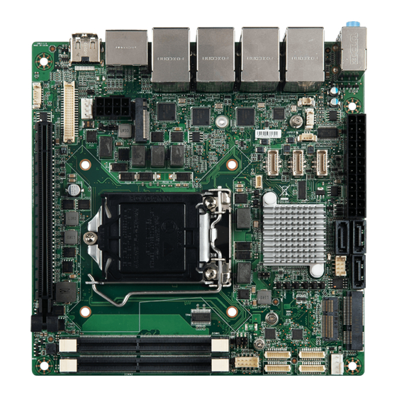
Page 14: Layout
Overview Layout S/PDIF Box COM Port AT/ATX Mini-PCIe Slot Header Power Jumper Jumper Amplifier ATX Power SATA 3.0 USB 2.0 M.2 E Key Slot Box Header Connector Connector Box Header Nano SIM Rear Panel Holder (backside) System Fan Connector GPIO Box Header USB 3.1 Gen 1... -
Page 15: Rear Panel I/O Options
MS-98L1 Rear Panel I/O Options SKU1 (C246) Line-In GbE LAN GbE LAN Line-Out USB 3.1 Gen 2 USB 3.1 Gen 1 DisplayPort HDMI Mic-In (DP by option) SKU2 (Q370) Line-In GbE LAN Line-Out USB 3.1 Gen 2 USB 3.1 Gen 1... -
Page 17: Hardware Setup
Hardware Setup This chapter provides you with the information about hardware setup procedures. While doing the installation, be careful in holding the components and follow the installation procedures. For some components, if you install in the wrong orientation, the components will not work properly. -
Page 18: Components Reference Guide
Hardware Setup Components Reference Guide SATA1 SATA3 SATA2 MINIPCIE1 SYSFAN1 JPWR1 JUSB4 JAMP1 JUSB3 M2_E1 JATX1 JCOMP2 JUSB2 JCOMP3 JSPDIF1 JCMOS1 JME_DIS1 JUSB1 JUSBD1 JCASE1 JSMB1 JUSBD2 M2_M1 J_CFG1 JINV1 CPUFAN1 JLVDS1 PCIE1 JINVT1... - Page 19 MS-98L1 Components Reference Guide ............2-2 CPU (Central Processing Unit) ............2-4 Introduction to LGA 115x CPU ..............2-4 CPU Installation ..................2-5 Memory ....................2-7 Dual-Channel Mode ...................2-7 Recommended Memory Population ............2-7 Installing Memory Modules ................2-8 Storage ....................2-9 Storage Support ..................2-9 Serial ATA Connector: SATA1, SATA2, SATA3 .........2-10 M2_M1: M.2 M Key 2242/2260/2280 Slot for SSD ........2-10...
-
Page 20: Cpu (Central Processing Unit)
Hardware Setup CPU (Central Processing Unit) When installing the CPU, make sure that you install the cooler to prevent overheating. If you do not have the CPU cooler, consult your dealer before turning on the computer. Important Overheating Overheating will seriously damage the CPU and system. Always make sure the cooling fan can work properly to protect the CPU from overheating. -
Page 21: Cpu Installation
MS-98L1 CPU Installation When you are installing the CPU, make sure the CPU has a cooler attached on the top to prevent overheating. Meanwhile, do not forget to apply some thermal paste on CPU before installing the heat sink/cooler fan for better heat dispersion. - Page 22 Hardware Setup 5. Secure the load lever with the hook 6. Make sure the four hooks are in under the retention tab. proper position before you install the cooler. Align the holes on the motherboard with the cooler. Push down the cooler until its four clips get wedged into the holes of the motherboard.
-
Page 23: Memory
MS-98L1 Memory Dual-Channel Mode In Dual-Channel mode, make sure that you install memory modules of the same type and density in different channel DIMM slots. Recommended Memory Population Number of DIMMs installed DIMM1 (ch A) DIMM2 (ch B) Important • "V" indicates a populated DIMM slot. -
Page 24: Installing Memory Modules
Hardware Setup Installing Memory Modules 1. 1Unlock the SO-DIMM slot by flipping open its side clips. 2. Vertically insert the SO-DIMM into the slot. The SO-DIMM has an off-center notch at the bottom that will only allow it to fit one way into the slot. Push the SO-DIMM deeply into the slot. -
Page 25: Storage
MS-98L1 Storage SATA1 SATA3 SATA2 M2_M1 Storage Support SKU1 (C246) SKU2 (Q370) SKU3 (H310) SKU4 (H310) Storage 3 * SATA 6Gb/s ports (RAID 0, 1, 5, 10 supported; 3 * SATA 6Gb/s ports SATA RAID 10 should configured with M.2;... -
Page 26: Serial Ata Connector: Sata1, Sata2, Sata3
Hardware Setup Serial ATA Connector: SATA1, SATA2, SATA3 This connector is a high-speed Serial ATA interface port. Each connector can connect to one Serial ATA device. Important Please do not fold the SATA cable into a 90-degree angle. Otherwise, data loss may occur during transmission. -
Page 27: Power Supply
MS-98L1 Power Supply JPWR1 Power Connectors: JPWR1, JPWR2 These connectors allow you to connect a power supply. JPWR2 Ground +12V Ground +12V Ground +12V Ground +12V 2-11... - Page 28 Hardware Setup +3.3V +3.3V +3.3V -12V Ground Ground PS-ON# Ground Ground JPWR1 Ground Ground Ground PWR OK 5VSB +12V +12V +3.3V Ground Important • Make sure all power connectors are connected to the power supply to ensure stable operation of the motherboard. •...
-
Page 29: Rear Panel I/O
MS-98L1 Rear Panel I/O SKU1 (C246) Line-In GbE LAN GbE LAN Line-Out USB 3.1 Gen 2 USB 3.1 Gen 1 DisplayPort HDMI Mic-In (DP by option) SKU2 (Q370) Line-In GbE LAN Line-Out USB 3.1 Gen 2 USB 3.1 Gen 1... - Page 30 Hardware Setup Audio Ports These audio connectors are used for audio devices. It is easy to differentiate between audio effects according to the color of audio jacks. ■ Line-In (Blue) - Line In, is used for external CD player, tape player or other audio devices.
-
Page 31: Connectors
MS-98L1 Connectors Fan Power Connectors: CPUFAN1, SYSFAN1 The fan power connector supports system cooling fans with +12V. When connecting the wire to the connectors, always note that the red wire is the positive and should be connected to the +12V; the black wire is Ground and should be connected to GND. -
Page 32: Front Panel Connector: Jfp1
Hardware Setup Front Panel Connector: JFP1 This front panel connector is provided for electrical connection to the front panel switches & LEDs. JFP1 9 10 HDD LED + Power LED + HDD LED - Power LED - Reset Switch - Power Switch + Reset Switch + Power Switch -... -
Page 33: Lvds Box Header: Jlvds1 (For Sku1 & Sku2)
MS-98L1 LVDS Box Header: JLVDS1 (For SKU1 & SKU2) The LVDS (Low Voltage Differential Signal) connector provides a digital interface typically used with flat panels. After connecting an LVDS interface flat panel to the JLVDS1, be sure to check the panel datasheet and set the LVDS jumper to proper power voltage. -
Page 34: Com Port Box Headers: Jcom1, Jcom2, Jcom3 (Optional)
Hardware Setup COM Port Box Headers: JCOM1, JCOM2, JCOM3 (Optional) This connector allows you to connect optional serial ports through brackets. SKU1 (C246) SKU2 (Q370) SKU3 (H310) SKU4 (H310) ■2 * RS232/422/485 ■1 * RS232/422/485 ■1 * RS232/422/485 COM Ports ■4 * RS232 ■3 * RS232 ■1 * RS232... -
Page 35: Amplifier Box Header: Jamp1 (For Sku1 & Sku2)
MS-98L1 Amplifier Box Header: JAMP1 (For SKU1 & SKU2) The JAMP1 is used to connect audio amplifiers to enhance audio performance. S/PDIF Box Header: JSPDIF1 (For SKU1 & SKU2) This pinheader is used to connect S/PDIF (Sony & Philips Digital Interconnect Format) interface for digital audio transmission. -
Page 36: Usb 2.0 Box Header: Jusb4 (For Sku1 & Sku2)
Hardware Setup USB 2.0 Box Header: JUSB4 (For SKU1 & SKU2) These connectors allow you to connect USB 2.0 ports on the front panel. USB 3.1 Gen 1 Connector: JUSB1, JUSB2, JUSB3 (For SKU1 & SKU2) This connector allows you to connect USB 3.1 Gen 1 ports on the front panel. JUSB1/ JUSB2/ JUSB3 USB3_PWR USB2_DP2... -
Page 37: Jumpers
MS-98L1 Jumpers Important Avoid adjusting jumpers when the system is on; it will damage the motherboard. JATX1 JCOMP2 JCOMP3 JCMOS1 JME_DIS1 JUSBD1 JUSBD2 J_CFG1 JINV1 Jumper Name Default Setting Description JCMOS1 1-2: Normal 2-3: Clear CMOS JATX1 1-2: ATX 2-3: AT... -
Page 38: Slots
Hardware Setup Slots PCIe (Peripheral Component Interconnect Express) Slot The PCI Express slot supports PCIe interface expansion cards. PCIe x16 slot Mini-PCIe (Peripheral Component Interconnect Express) Slot The Mini-PCIe slot is provided for WiFi modules, Bluetooth modules, TV tuner cards and other Mini-PCIe cards. M2_E1: M.2 E Key 2230 Slot for WiFi/BT (For SKU1 &... -
Page 39: Bios Setup
BIOS Setup This chapter provides information on the BIOS Setup program and allows users to configure the system for optimal use. Users may need to run the Setup program when: ■ An error message appears on the screen at system startup and requests users to run SETUP. -
Page 40: Entering Setup
BIOS Setup Entering Setup Power on the computer and the system will start POST (Power On Self Test) process. When the message below appears on the screen, press <DEL> or <F2> key to enter Setup. Press <DEL> or <F2> to enter SETUP If the message disappears before you respond and you still wish to enter Setup, restart the system by turning it OFF and On or pressing the RESET button. - Page 41 MS-98L1 Control Keys ← → Select Screen ↑ ↓ Select Item Enter Select Change Option General Help Previous Values Optimized Defaults Save & Reset Exit Getting Help After entering the Setup menu, the first menu you will see is the Main Menu.
-
Page 42: The Menu Bar
BIOS Setup The Menu Bar ▶ Main Use this menu for basic system configurations, such as time, date, etc. ▶ Advanced Use this menu to set up the items of special enhanced features. ▶ Boot Use this menu to specify the priority of boot devices. ▶... -
Page 43: Main
MS-98L1 Main ▶ System Date This setting allows you to set the system date. The date format is <Day>, <Month> <Date> <Year>. ▶ System Time This setting allows you to set the system time. The time format is <Hour> <Minute> <Second>. -
Page 44: Advanced
BIOS Setup Advanced ▶ Full Screen Logo Display This BIOS feature determines if the BIOS should hide the normal POST messages with the motherboard or system manufacturer’s full-screen logo. When it is enabled, the BIOS will display the full-screen logo during the boot-up sequence, hiding normal POST messages. - Page 45 MS-98L1 ▶ CPU Configuration ▶ Intel Virtualization Technology Virtualization enhanced by Intel Virtualization Technology will allow a platform to run multiple operating systems and applications in independent partitions. With virtualization, one computer system can function as multiple “Virtual” systems. ▶ Active Processor Cores This setting specifies the number of active processor cores.
- Page 46 BIOS Setup ▶ Super IO Configuration ▶ Serial Port 1/ 2/ 3/ 4/ 5/ 6 This setting enables/disables the specified serial port. ▶ Change Settings This setting is used to change the address & IRQ settings of the specified serial port. ▶...
- Page 47 MS-98L1 ▶ H/W Monitor These items display the current status of all monitored hardware devices/ components such as voltages, temperatures and all fans’ speeds. ▶ Smart Fan Configuration ▶ CPUFAN1, SYSFAN1 This setting enables/disables the Smart Fan function. Smart Fan is an...
- Page 48 BIOS Setup ▶ Network Stack Configuration This menu provides Network Stack settings for users to enable network boot (PXE) from BIOS. ▶ PCI/PCIE Device Configuration ▶ Legacy USB Support Set to [Enabled] if you need to use any USB 1.1/2.0 device in the operating system that does not support or have any USB 1.1/2.0 driver installed, such as DOS and SCO Unix.
- Page 49 MS-98L1 ▶ Launch OnBoard LAN OpROM These settings enable/disable the initialization of the onboard/onchip LAN Boot ROM during bootup. Selecting [Disabled] will speed up the boot process. ▶ GPIO Group Configuration ▶ GPO0 ~ GPO7 These settings control the operation mode of the specified GPIO.
-
Page 50: Boot
BIOS Setup Boot ▶ CSM Support This setting enables/disables the support for Compatibility Support Module, a part of the Intel Platform Innovation Framework for EFI providing the capability to support legacy BIOS interfaces. ▶ Boot Option Priorities This setting allows users to set the sequence of boot devices where BIOS attempts to load the disk operating system. -
Page 51: Security
MS-98L1 Security ▶ Administrator Password Administrator Password controls access to the BIOS Setup utility. ▶ User Password User Password controls access to the system at boot and to the BIOS Setup utility. ▶ Chassis Intrusion The field enables or disables the feature of recording the chassis intrusion status and issuing a warning message if the chassis is once opened. - Page 52 BIOS Setup ▶ PCH-FW Configuration ▶ ME Firmware Version, ME Firmware Mode, ME Firmware SKU, ME Firm- ware Status 1, ME Firmware Status 2 These settings show the firmware information of the Intel ME (Management Engine). ▶ ME State This setting enables/disables the ME status. ▶...
- Page 53 MS-98L1 ▶ ME Unconfig on RTC Clear This setting enables/disables ME firmware unconfigure on RTC clear. ▶ Comms Hub Support This setting enables/disables Communications Hub Support. ▶ JHI Support This setting enables/disables support for Intel Dynamic Application Loader Host Interface (JHI).
- Page 54 BIOS Setup ▶ PTT Configuration Intel Platform Trust Technology (PTT) is a platform functionality for credential storage and key management used by Microsoft Windows. ▶ ME Debug Configuration 3-16...
- Page 55 MS-98L1 ▶ Anti-Rollback SVN Configuration ▶ Trusted Computing ▶ Security Device Support This setting enables/disables BIOS support for security device. When set to [Disable], the OS will not show security device. TCG EFI protocol and INT1A interface will not be available.
- Page 56 BIOS Setup ▶ Pending Operation When Security Device Support is set to [Enable], Pending Operation will appear. Set this item to [TPM Clear] to clear all data secured by TPM or [None] to discard the selection. It is advised that users should routinely back up their TPM secured data.
- Page 57 MS-98L1 ▶ Console Redirection Settings ▶ Terminal Type To operate the system’s console redirection, you need a terminal supporting ANSI terminal protocol and a RS-232 null modem cable connected between the host system and terminal(s). This setting specifies the type of terminal device for console redirection.
- Page 58 BIOS Setup Legacy Console Redirection ▶ Legacy Console Redirection Settings ▶ Redirection COM Port This setting specifies the COM port for redirection. ▶ Resolution This setting specifies the redirection resolution of legacy OS. ▶ Redirect After POST This setting determines whether or not to keep terminals’ console redirection running after the POST has booted.
- Page 59 MS-98L1 ▶ Console Redirection Settings ▶ Out-of-Band Mgmt Port This setting specifies the Out-of-Band Management Port. ▶ Terminal Type To operate the system’s console redirection, you need a terminal supporting ANSI terminal protocol and a RS-232 null modem cable connected between the host system and terminal(s).
-
Page 60: Chipset
BIOS Setup Chipset ▶ Primary Display Use the field to select the type of device you want to use as the display(s) of the system. ▶ DVMT Total Gfx Mem This setting specifies the memory size for DVMT. ▶ Primary IGFX Boot Display Use the field to select the primary IGFX boot display of the system. -
Page 61: Power
MS-98L1 Power ▶ Restore AC Power Loss This setting specifies whether your system will reboot after a power failure or interrupt occurs. Available settings are: [Power Off] Leaves the computer in the power off state. [Power On] Leaves the computer in the power on state. - Page 62 BIOS Setup ** Advanced Resume Events Control ** ▶ OnChip GbE/USB This field specifies whether the system will be awakened from power saving modes when activity or input signal of onchip LAN or USB devices is detected. ▶ PCIE/Ring PME This field specifies whether the system will be awakened from power saving modes when activity or input signal of onboard PCIE/PCI/Ring PME is detected.
-
Page 63: Save & Exit
MS-98L1 Save & Exit ▶ Save Changes and Reset Save changes to CMOS and reset the system. ▶ Discard Changes and Exit Abandon all changes and exit the Setup Utility. ▶ Discard Changes Abandon all changes. ▶ Load Optimized Defaults Use this menu to load the default values set by the motherboard manufacturer specifically for optimal performance of the motherboard. -
Page 65: Appendix Gpio Wdt Bkl Programming
Appendix GPIO WDT BKL Programming This appendix provides WDT (Watch Dog Timer), GPIO (General Purpose Input/ Output) and LVDS Backlight programming guide. 2-A-1... -
Page 66: Abstract
GPIO WDT BKL Programming Abstract Abstract In this document, code examples based on C programming language provided for customer interest. Inportb, Outportb, Inportl and Outportl are basic functions used for access IO ports and defined as following. Inportb: Read a single 8‐bit I/O port. Outportb: Write a single byte to an 8‐bit port. Inportl: Reads a single 32‐bit I/O port. Outportl: Write a single long to a 32‐bit port. ... -
Page 67: General Purposed Io
MS-98L1 General Purposed IO 1. General Purposed IO – GPIO/DIO The GPIO port configuration addresses are listed in the following table: Name IO Port IO address Name IO Port IO address N_GPI0 0x42 Bit 0 N_GPO0 0x11 Bit 0 N_GPI1 0x42 Bit 1 N_GPO1 0x11 Bit 1 N_GPI2 N_GPO2 0x42 Bit 2 0x11 Bit 2 N_GPI3 0x42 Bit 3 N_GPO3 0x11 Bit 3 N_GPI4 0x42 Bit 4... -
Page 68: Watchdog Timer
GPIO WDT BKL Programming Watchdog Timer 2. Watchdog Timer – WDT The base address (WDT_BASE) of WDT configuration registers is 0xA10. Set WDT Time Unit val = Inportb (WDT_BASE + 0x05); // Read current WDT setting val = val | 0x08; // minute mode. val = val & 0xF7 if second mode Outportb (WDT_BASE + 0x05, val); // Write back WDT setting Set WDT Time Outportb (WDT_BASE + 0x06, Time); // Write WDT time, value 1 to 255. Enable WDT val = Inportb (WDT_BASE + 0x0A); // Read current WDT_PME setting val = val | 0x01; ... -
Page 69: Lvds Backlight Brightness Control
MS-98L1 LVDS Backlight Brightness Control 3. LVDS Backlight Brightness Control The LVDS controller support 17 level of backlight brightness value from 0 (30%) to 16 (100%) and it is accessible through SMBus. The associated access method (SMBus_ReadByte, SMBus_WriteByte) provided in part 4. Set the Level of LVDS Backlight 1. Write 0xED into address 0x7F on SMBus device 0x42. 2. Write desired backlight level from 0x0 (30%) to 0x10 (100%) into address 0x6E on ... -
Page 70: 4. Smbus Access
GPIO WDT BKL Programming SMBus Access 4. SMBus Access The base address of SMBus must know before access. The relevant bus and device information are as following. #define IO_SC 0xCF8 #define IO_DA 0xCFC #define PCIBASEADDRESS 0x80000000 #define PCI_BUS_NUM 0 #define PCI_DEV_NUM 31 #define PCI_FUN_NUM ...
Need help?
Do you have a question about the MS-98L1 and is the answer not in the manual?
Questions and answers