Table of Contents
Advertisement
Quick Links
We advise you to read this manual carefully, which contains all the instructions for
maintaining the appliance's aesthetic and functional qualities.
For further information on the product: www.smeg.com
Contents
40
40
41
41
41
41
42
42
43
43
43
44
45
45
47
47
48
48
50
50
51
53
54
58
58
58
59
60
60
61
63
63
66
71
72
39
Advertisement
Table of Contents

Subscribe to Our Youtube Channel
Related Manuals for Smeg TR90DGC


Summary of Contents for Smeg TR90DGC
-
Page 1: Table Of Contents
5.2 Adaptation to different types of gas 5.3 Electrical connection 5.4 Positioning We advise you to read this manual carefully, which contains all the instructions for maintaining the appliance's aesthetic and functional qualities. For further information on the product: www.smeg.com... -
Page 2: Instructions
Instructions 1 Instructions • Have qualified personnel carry out installation and assistance 1.1 General safety instructions interventions according to the standards in force. Risk of personal injury • Do not modify this appliance. • During use the appliance and its •... -
Page 3: Identification Plate
Instructions • Use wooden or plastic utensils. 1.3 Manufacturer liability • Do not seat on the appliance. The manufacturer declines all liability for damage to persons or property caused by: • Do not use steam jets for cleaning the • use of the appliance other than the one appliance. -
Page 4: This User Manual
Instructions • Consign the appliance to the 1.7 How to read the user manual appropriate selective collection centres This user manual uses the following reading for electrical and electronic equipment conventions: waste, or deliver it back to the retailer Instructions when purchasing an equivalent product, on a one for one basis. -
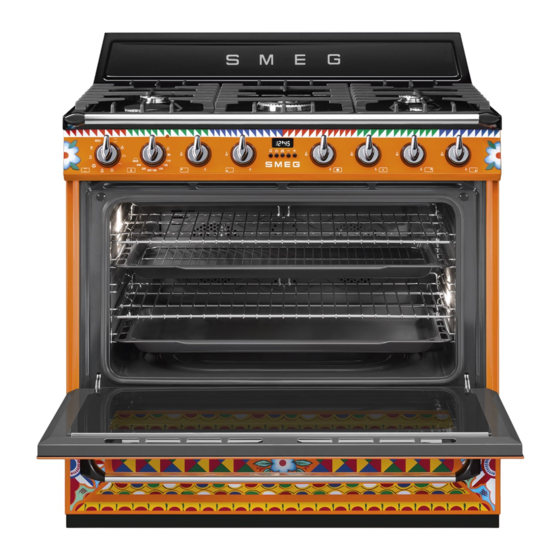
Page 5: Description
Description 2 Description 2.1 General Description 1 Backguard 6 Door 2 Cooking hob 7 Fan 3 Control panel 8 Storage compartment 4 Oven light Rack/tray support frame shelf 5 Seal 2.2 Cooking hob AUX = Auxiliary UR2 int = internal crown ultra rapid SR = Semi-rapid UR2 est = external crown ultra rapid R = Rapid... -
Page 6: Control Panel
Description 2.3 Control panel 1 Temperature knob 4 Hob burner knobs This knob allows you to select the cooking Useful for lighting and adjusting the hob temperature. burners. Press and turn the knobs anti-clockwise to Turn the knob clockwise to the required the value to light the relative burners. -
Page 7: Other Parts
Description 2.4 Other parts 2.5 Available accessories Shelves Some models are not provided The appliance features shelves for with all accessories. positioning trays and racks at different heights. The insertion heights are indicated Reduction pan stand from the bottom upwards (see 2.1 General Description). - Page 8 Description Oven tray Rotisserie handle Useful for taking the rotisserie rod out of the oven. Useful for collecting fat from foods placed Self-cleaning panels on the rack above. Rotisserie rod Useful for absorbing small grease residues. The accessories intended to come into contact with food are made of materials that comply with the Useful for cooking chicken and all foods...
-
Page 9: Use
3 Use Improper use Risk of damage to surfaces 3.1 Instructions High temperature inside the oven • Do not cover the bottom of the oven during use cavity with aluminium or tin foil sheets. Danger of burns • If you wish to use greaseproof paper, place it so that it will not interfere with the •... -
Page 10: First Use
3.3 Using the accessories High temperature inside the oven during use Racks and trays Danger of fire or explosion Racks and trays have to be inserted into the side guides until they come to a complete • Do not spray any spray products near stop. - Page 11 sure that the contoured part is placed • correctly on the guide frame and remove the handle. 4. To activate the rotisserie, turn the function Rotisserie rod knob to position 1. Prepare the rotisserie rod with the food using the clip forks provided. Grill + rotisserie cooking must never exceed 240°C and must not last more than 30 minutes.
-
Page 12: Using The Storage Compartment
Reduction pan stands 3.5 Using the hob All the appliance's control and monitoring The reduction pan stands have to be devices are located together on the front placed on the hob grids. Make sure they panel. The burner controlled by each knob are properly placed. -
Page 13: Using The Oven
3.6 Using the oven Correct positioning of the flame- spreader crowns and burner caps Switching on the oven Before lighting the hob burners, make sure To switch on the oven: that the flame-spreader crowns are 1. Select the cooking function using the correctly positioned in their housings with function knob. - Page 14 Grill + rotisserie Fan + circulaire The rotisserie works in combination The combination of the fan and the with the central grill heating element circulaire heating element and allows food to be perfectly (incorporated in the rear of the browned. oven) allows you to cook different foods on several levels, as long as they need the same temperatures...
-
Page 15: Cooking Advice
3.7 Cooking advice • Foods should be seasoned before cooking. Foods should also be coated General advice with oil or melted butter before cooking. • Use a fan assisted function to achieve • Use the oven tray on the first bottom shelf consistent cooking at several levels. -
Page 16: Programmer Clock
Advice for defrosting and proving 3.8 Programmer clock • Place frozen foods without their packaging in a lidless container on the first shelf of the oven. • Avoid overlapping the food. • To defrost meat, use the rack placed on the second level and a tray on the first level. - Page 17 activate. The current time and the Setting the time symbols will appear on the If the time is not set, the oven will display. not switch on. 4. At the end of cooking the heating elements will be deactivated. On the On the first use, or after a power failure, the display, symbol turns off, symbol...
- Page 18 3. Wait approx. 5 seconds without pressing 3. Use the key to set the required any key to finish setting the minute minutes. minder. The current time and the symbols 4. Wait approx. 5 seconds without pressing appear on the display. any key in order for the function to activate.
- Page 19 Cooking information table Runner posi- Weight Temperature Food Function tion from the Time (minutes) (Kg) (°C) bottom Lasagne 3 - 4 Static 220 - 230 45 - 50 Pasta bake 3 - 4 Static 220 - 230 45 - 50 Roast veal Turbo/Fan assisted 180 - 190...
-
Page 20: Cleaning And Maintenance
Cleaning and maintenance 4 Cleaning and maintenance Food stains or residues Do not use metallic sponges or sharp 4.1 Instructions scrapers as they will damage the surfaces. Use ordinary non-abrasive products with Improper use the aid of wooden or plastic utensils if Risk of damage to surfaces necessary. -
Page 21: Removing The Door
Cleaning and maintenance 4.3 Removing the door Flame-spreader crowns and burner caps For easier cleaning, the door can be For easier cleaning, the flame-spreader removed and placed on a canvas. crowns and the burner caps can be removed. Wash them in hot water and non- To remove the door proceed as follows: abrasive detergent. -
Page 22: Cleaning The Door Glazing
Cleaning and maintenance and once it is in place remove the pins Removing racks/trays support frames from the holes in the hinges. Removing the rack/tray support frames enables the sides to be cleaned more easily. Removing the rack/tray support frames: 1. -
Page 23: Extraordinary Maintenance
Cleaning and maintenance 4.6 Extraordinary maintenance Regeneration of self-cleaning panels (catalytic cycle) Live parts The regeneration cycle of the self-cleaning Danger of electrocution panels is a cleaning method through heating suitable for removing small grease • Disconnect the oven power supply. residues, not sugar-based ones. - Page 24 Cleaning and maintenance Removing the seal of the oven 4. Slide out and remove the lamp. To permit thorough cleaning of the oven, the door seal may be removed. There are fasteners on all 4 sides and in the middle to attach it to the edge of the oven.
-
Page 25: Installation
Installation 5 Installation Connection with a rubber hose Verify that all following conditions are met: 5.1 Gas connection • the hose is fixed to the hose connection with safety clamps; Gas leak • no part of the hose is in contact with hot Danger of explosion walls (max. - Page 26 Installation After having tightened the hose Carefully screw the connector 3 to the gas connector(s), push the gas hose 6 onto the connector 1 of the appliance, placing the hose connector and secure it with the clamp seal 2 between them. 5 that is compliant with the standard in force.
- Page 27 Installation Connection with a flexible steel hose with Room ventilation conical fitting The appliance should be installed in rooms Make the connection to the gas mains that have a permanent air supply in using a continuous wall flexible steel hose accordance with the standards in force.
-
Page 28: Adaptation To Different Types Of Gas
Installation When the job is complete, the installer must 5.2 Adaptation to different types of issue a certificate of conformity. In case of operation with other types of gas, the burner nozzles must be changed and the minimum flame adjusted on the gas taps. - Page 29 Installation Adjusting the minimum setting for natural Adjusting the minimum setting for LPG or city gas Tighten the screw located at the side of the Light the burner and turn it to the minimum tap rod clockwise all the way. position.
- Page 30 Installation Gas types and Countries Gas types IT GB-IE FR-BE DE RU DK 1 Natural Gas G20 20 mbar • • • • • • • • • G20/25 20/25 mbar • 2 Natural Gas G20 25 mbar • 3 Natural Gas G25 25 mbar •...
- Page 31 Installation Burner and nozzle characteristics tables 1 Natural Gas G20 UR2 int. Rated heating capacity (kW) Nozzle diameter (1/100 mm) Pre-chamber (printed on nozzle) (H1) (H4) Reduced capacity (W) 1600 2 Natural Gas G20 UR2 int. Rated heating capacity (kW) Nozzle diameter (1/100 mm) Pre-chamber (printed on nozzle) (H8)
- Page 32 Installation 8 LPG G30/31 UR2 int. Rated heating capacity (kW) Nozzle diameter (1/100 mm) Pre-chamber (printed on nozzle) Reduced capacity (W) 1600 Rated capacity G30 (g/h) Rated capacity G31 (g/h) 9 LPG G30/31 UR2 int. Rated heating capacity (kW) Nozzle diameter (1/100 mm) Pre-chamber (printed on nozzle) Reduced capacity (W) 1600...
-
Page 33: Electrical Connection
Installation 5.3 Electrical connection The appliance can work in the following modes: Power voltage • 220-240 V 1N~ Danger of electrocution • Have the electrical connection performed by authorised technical personnel. Use a 3 x 2.5 mm² three-core cable. • Use personal protective equipment. •... -
Page 34: Positioning
Installation Fixed connection General information Fit the power line with an omnipolar circuit This appliance may be installed next to breaker in compliance with installation walls, one of which must be higher than the regulations. worktop, at a minimum distance of 50 mm from the side of the appliance, as shown in The circuit breaker should be located near figures A and C relative to the installation... - Page 35 Installation Assembling the backguard The backguard provided is an integral part of the product; it must be fastened to the appliance prior to installation. The backguard must always be positioned and secured correctly on the appliance. 1. Loosen the 6 screws on the back of the top (A) and unscrew the 2 screws (B) on the side part of the backguard.
- Page 36 Installation Positioning and levelling the appliance Mounting the toe skirt After making the electrical and/or gas The toe skirt provided is an integral connections, properly level the appliance part of the product; it must be on the floor to ensure better stability. Screw fastened to the appliance prior to or unscrew the bottom part of the foot until installation.
Need help?
Do you have a question about the TR90DGC and is the answer not in the manual?
Questions and answers