Table of Contents
Advertisement
Quick Links
Advertisement
Table of Contents

Related Manuals for Kilews KFA-0850H


Summary of Contents for Kilews KFA-0850H
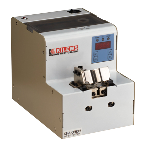
- Page 1 AUTOMATIC SCREW FEEDER KFA-0850H (PICK UP TYPE) Instruction Manual (ENGLISH) Please read this manual thoroughly, before operating the unit and retain it for future reference. Patented in China, Taiwan, Japan & Korea. Imitation of product will be caused prosecution. Y2F152-5-003...
- Page 2 SAFETY INSTRUCTIONS PLEASE NOTE FOLLOWING CONDITIONS BEFORE USING KILEWS KFA-0850 ◎ For a normal performance, please install this machine on a flat and stable working table, do not slant or pad, otherwise machine function might be affected. ◎ Turn off the power switch and unplug the AC adaptor when this machine is not being used for a period of time.
-
Page 3: Table Of Contents
CONTENTS CHECK BEFORE OPERATION…………………………..………………………1 ACCESSORIES INCLUDED…………………………………………………….1 CHECK THE SCREW SIZE ………………………..……………………..…1 FUNCTIONS WITH ADJUSTING HOLES ON HOUSING AND PCB ……..2 ADJUSTMENT………………………………………………………………………3 ADJUST THE RAIL ASSEMBLY…………………………………………………3 DISMANTLE THE RAIL ASSEMBLY………………………………………….3 ADJUST THE WIDTH OF RAIL ASSMEBLY…………………………………6 INSERT THE RAIL ASSEMBLY……………………………………………….8 ADJUST THE HOLDING PLATE……………………………………………….10 ADJUST THE FEEDING STRUCTURE……………………………………….11 ADJSUT THE SENSOR FUNCTION…………………………………………..13... -
Page 4: Check Before Operation
CHECK BEFORE OPERATION ACCESSORIES INCLUDED Please check if there are complete accessories included with your KFA-0820H: HEX Wrench 2.0*107mmL Type*1 Power Controller AC 100~240V/DC12V*1 Orbit Back-End Chip Rule Orbit Front-End Chip Rule 20*10*0.2mm*2pcs&0.5mm*6pcs 20*10*0.2mm*2pcs&0.5mm*6pcs Instruction Manual*1 CHECK THE SCREW SISE Measure the size precisely on each part of applied screw with a caliper. -
Page 5: Functions With Adjusting Holes On Housing And Pcb
※ Attention ※ a. Part F, G, H are installed and set properly by Kilews, please do not adjust by your own. b. Part F、G、H are installed in the inside of PCB, please do not use any tools and adjust it by... -
Page 6: Adjustment
ADJUSTMENT After checking the screw size, it needs to adjust all related parts according to the screw size for the first use. ADJUST THE RAIL ASSEMBLY Remove the fixing screws of guide assembly, dismantle the guide assembly. Remove the fixing screws (6pcs) of front housing, and take off the front housing. - Page 7 3. Dismantle the fixing screws (4pcs) of feeding structure, and take it off. 4. Facing the machine, use Hex wrench to loose the screw clockwise to open the lock gate upward. 5. Facing the machine, use Hex wrench to loose the screw clockwise to open the lock gate rightward.
- Page 8 6. Remove the fixing screws of rail assembly The fixing screws of rail assembly 7. Draw out the rail assembly from the machine. ※NOTE THE FOLLOWING WHEN MAKING ABOVE ADJUSTMENT※ a. Before dismantle the rail assembly, please confirm the lock gate status is open.
-
Page 9: Adjust The Width Of Rail Assmebly
ADJUST THE WIDTH OF RAIL ASSEMBLY 1. Remove the fixing screws on the front end of rail assembly. 2. Remove the fixing screw on the rear end of side of rail assembly, take off the tooling plate 3. According to Table b, insert the suitable tooling plate into the rail groove for the width required and tighten the screw of step 1.2. - Page 10 ※ COMBINATION OF THE THICKNESS FOR REFERENCE ※Table b Dia. of Screw Bolt Accessory-Tooling Dia. of Screw Accessory-Tooling (d) mm Plate (Rear) mm Bolt (d) mm Plate (Rear) mm 0.5*2+0.2*2=1.4 0.2 + 0.5 * 5 = 2.7 0.2*3+0.5 *2 = 1.6 0.2 + 0.5 * 6 = 3.2 0.2 * 2 + 0.5 * 3 = 1.9 0.2 + 0.5 * 7 = 3.7...
-
Page 11: Insert The Rail Assembly
INSTALL THE RAIL ASSEMBLY Insert the adjusted rail assembly into the machine. Then fasten the fixing screws. Install the feeding structure, and then fasten screws. - Page 12 Adjust up and right gate to make distance between rail and gate around 0.2~0.5mm. 0.2~0.5mm Loosen rail fixing screw, adjust distance between the front of rail and disc around 0.2~0.5mm, fasten the screw. 0.2~0.5mm ※ NOTE a. Rail installation must keep 0.2~0.5mm gap with disc, must not be touched. b.
-
Page 13: Adjust The Holding Plate
Force-down plate adjustment 1. Loosen fixing screw on force-down plate. 2. Use accessory tooling plate adjust height of force-down plate and then fasten screw in step1. 3. Put some screws into the groove and slide it up, to check whether the movement is smooth. -
Page 14: Adjust The Feeding Structure
Distribution Mechanism adjustment 1. Loosen fixing screw from front of distribution mechanism. 2. Align disc gap with central of rail by adjust front of distribution mechanism by left and right, fasten the loosen screw in step 1. 3. Loosen two hexagon screws. - Page 15 4. Adjust from part by up and down to make disc and rail flush, and then fasten loosen screw in step 3. Flush ※ NOTE ※ a. Align disc gap with central of rail, and upper plane cannot higher than upper plane of front rail.
-
Page 16: Adjsut The Sensor Function
Adjust Sensor Function 1. Loosen the fixing screw of sensor fixing plate 2. Make sure to cover half of the hole, and then fasten the screw of step 1. ※ NOTICE ※ Make sure to cove half of the hole, and do adjustment to ensure the sensor function no problem. -
Page 17: Adjust The V Chase On Roller
Adjust V Chase on Scooping Chamber Back The V Chase is locate on top of the rail, and fastened to the back of Roller Assembly. The purpose is to catch fallen screws from the Rollers, and guide screws back to the rail. 1. -
Page 18: Adjust The Brush
Adjust the Brush 1. Swing the brush to stay almost horizontal, loosen screw on the side of brush bracket. 2. Place 5~8 screws into the rail groove close to the holding plate rear end and loosen 2 screws on the side of the brush bracket. Swing the brush and adjust the height until the brush just touch the screw heads slightly, and tighten the screws after adjustment. -
Page 19: Operation Method
Method of Operation Load Screws Into the Chamber Turn off the power first, and open the Top Cover Box. Ensure the screws are loaded without foreign materials, pour in screws until they come up to 1~2mm below the top on both sides of the rails. -
Page 20: Picking Up Screw
PICK UP SCREWS Make sure the bit type onyour electric screwdriver matches the head of the screw, and the bit is magnetized before use.(Bit that not magnetized willnot stick with the screw andscrew willfall offafter picking up). Hold the screwdriver and put the driver bit above the Bit Guideand push it straight down to "+"... -
Page 21: Counter Interface Operation
Counter interface operation Display interface diagram Function of the Button SET:Setting mode UP:Upper(Increase button) OK:Confirm(Counter function) DOWN:Lower(Decrease button) Operation function and description a. Count State:Automatic counting state and set the counting state, press the OK key to switch. b. Restore the factory state In the standby or working state press the SET button and OK button at the same time for 3Sec, LED display flashes 3Sec and buzzing prompts the system to restore factory settings. - Page 22 3.2 In the standby or working state, press SET button 2 times to enter the system of increasing, ,00 as increment mode,01 as easing mode,LED flashes and display as decrement mode,press up or down button to change it, (System defaults as 00) ,Press the OK button within 3sec or 3sec does not press the button;...
- Page 23 3.6 In the standby or working state, press SET button 6 times to enter the system of roller delay ,press UP or Down button to time setting,,LED flashes and display as change the setting of delay time(system defaults time of roller delay time is based on the property of screw type ,...
-
Page 24: Maintenance & Trouble Shooting
3.10 In the standby or working state, press SET button 10 times to enter the system for , 00 to turn off reclaimer and roller setting, LED flashes and display as this function, press UP or Down button to change the setting(system defaults as 00, setting range 01-20). - Page 25 Troubleshooting Please power off for examination once needed Status Caused Solution No AC power or loose cable Check the power controller Screws quantity too much Take some screws out No action after power on Switch, motor, PCB malfunction Replace Switch, motor or PCB or come with abnormal Clean it up Screws fall in to the inside of machine...
-
Page 26: Maintenance & Cleaning
MAINTENANCE & CLEANING Turn off the POWER before performing maintenance and cleaning. CLEANING AND MAINTENANCE THE BRUSH Using the dry cotton to wipe the brush to remove the dust, Swing the brush by hand and adjust the height of the brush to make the brush in touch with screw heads. Replace the brush when brush hair is too worn and cannot wipe down screws in an improper position. - Page 27 WARRANTY CARD The warranty is valid for 12 months from purchase date (based on 8 working hours a day). Please contact your supplier during the warranty period for repair or maintenance. ❖ NOTE: 1. The service cost shall be considered as chargeable if the failure/cost was induced by any of the following conditions: -Failure due to improper handling or un-authorized modification.
- Page 28 WARRANTY CARD CUSTOMER: TELEPHONE: ADDRESS: PURCHASE DATE: DISTRIBUTOR: MODEL NAME AUTOMATIC SCREW FEEDER (PICK UP TYPE) MODEL NO. SERIAL NO. SCREW SIZE 1.2~5.0mm SWITCHING ADAPTOR DC IN 12V MACHINE : 182(L)*124(W)*147(H)mm MEASUREMENT EACH CARTON :282(L)*142(W)*201(H)mm N.W 3.1kg WEIGHT G.W 3.67kg Remark:...
Need help?
Do you have a question about the KFA-0850H and is the answer not in the manual?
Questions and answers