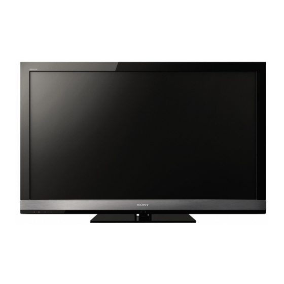
Sony KDL-40EX703 Service Manual
Az1-l chassis
Hide thumbs
Also See for KDL-40EX703:
- Electrical service manual (78 pages) ,
- Service manual (68 pages) ,
- Setup manual (52 pages)
Table of Contents
Advertisement
HISTORY INFORMATION FOR THE FOLLOWING MANUAL:
SERVICE MANUAL
SERVICE MANUAL
ORIGINAL MANUAL ISSUE DATE: 1/2010
Version
Date
1.0
1/25/2010
2.0
1/29/2010
3.0
3/17/2010
Subject
No revisions or updates
Corrected part information for Lens. Replaced pages i, 16-18.
Corrected Disassembly/Part Number Information section. Replaced pages 12-20.
Corrected Service Adjustment Information. Reissue entire manual.
AZ1-L
Chassis
LCD Digital Color TV
9-888-268-03
Advertisement
Table of Contents

Related Manuals for Sony KDL-40EX703


Summary of Contents for Sony KDL-40EX703
- Page 1 HISTORY INFORMATION FOR THE FOLLOWING MANUAL: SERVICE MANUAL SERVICE MANUAL AZ1-L Chassis ORIGINAL MANUAL ISSUE DATE: 1/2010 Version Date Subject 1/25/2010 No revisions or updates 1/29/2010 Corrected part information for Lens. Replaced pages i, 16-18. 3/17/2010 Corrected Disassembly/Part Number Information section. Replaced pages 12-20. Corrected Service Adjustment Information.
- Page 2 Self Diagnosis Supported model SERVICE MANUAL SERVICE MANUAL AZ1-L Chassis LCD Digital Color TV 9-888-268-03...
- Page 3 DESTINATION KDL-32EX700 RM-YD033 KDL-52EX700 RM-YD033 KDL-32EX700 RM-YD055 CND/MX KDL-52EX700 RM-YD055 CND/MX KDL-40EX700 RM-YD033 KDL-52EX701 RM-YD033 KDL-40EX700 RM-YD055 CND/MX KDL-52EX701 RM-YD055 KDL-40EX703 RM-YD055 KDL-52EX703 RM-YD055 KDL-46EX700 RM-YD033 KDL-60EX700 RM-YD033 KDL-46EX700 RM-YD055 CND/MX KDL-60EX700 RM-YD055 CND/MX KDL-46EX701 RM-YD033 KDL-60EX701 RM-YD033 KDL-46EX701 RM-YD055...
-
Page 4: Table Of Contents
TABLE OF CONTENTS Specifi cations....................................1 Warnings and Cautions ..................................3 Safety-Related Warning ..................................5 Safety Check-Out ....................................6 Self Diagnosis Functions ................................8 SEC 1. Disassembly/Part Number Information ..........................12 1-1. Table-Top Stand Assembly Removal ..........................12 1-2. Rear Cover, Switch Unit, and Power Switch Removal ....................13 1-2-1. - Page 5 TABLE OF CONTENTS 1-7. Connectors ..................................19 1-7-1. KDL-32EX700 .................................... 19 1-7-2. KDL-40EX700/40EX703 ................................19 1-7-3. KDL-46EX700/46EX701/46EX703 ............................20 1-7-4. KDL-52EX700/52EX701/52EX703 ............................20 1-7-5. KDL-60EX700/60EX701/60EX703 ............................20 1-8. Accessories and Packaging ............................21 1-9. Miscellaneous ................................21 1-10. Remote Commander ..............................21 SEC 2. Service Adjustments ................................22 2-1.
- Page 6 TABLE OF CONTENTS SEC 3. Diagrams ...................................30 3-1. Circuit Boards Location ..............................30 3-1-1. KDL-32EX700 .................................... 30 3-1-2. KDL-40EX700/40EX703 ................................31 3-1-3. KDL-46EX700/46EX701/46EX703 ............................32 3-1-4. KDL-52EX700/52EX701/52EX703 ............................33 3-1-5. KDL-60EX700/60EX701/60EX703 ............................34 3-2. Block Diagram ................................35 KDL-32EX700/40EX700/40EX703/46EX700/46EX701/46EX703/ 52EX700/52EX701/52EX703/60EX700/60EX701/60EX703...
-
Page 7: Specifications
“XrossMediaBar” is a trademark of Sony 40EX700 60EX700 52EX700 46EX700 registered in the U.S. and other countries. Corporation. “XMB” is a trademark of Sony Corporation and Sony Computer System HDMI, the HDMI logo and High-Definition Entertainment Inc. Multimedia Interface are trademarks or... - Page 8 SPECIFICATIONS Model name KDL- 60EX703 52EX703 46EX703 40EX703 60EX701 52EX701 46EX701 32EX700 40EX700 60EX700 52EX700 46EX700 Power and others Power requirement 110-240 V AC, 50/60 Hz (U.S.A./Canada 120 V AC, 60 Hz) Power consumption 208 W 142 W 125 W 107 W 91 W in use...
-
Page 9: Warnings And Cautions
Components identifi ed by shading and ! mark on the exploded views are critical for safe operation. Replace all components with Sony parts whose part numbers appear as shown in this manual or in supplements published by Sony. It is essential that all critical parts be replaced only with the part number specifi... - Page 10 Les composants identifi es par une trame et par une marque ! sur les schemas de principe, les vues explosees et les listes de pieces sont d’une importance critique pour la securite du fonctionnement. Ne les remplacer que par des composants Sony dont le numero de piece est indique dans le present manuel ou dans des supplements publies par Sony.
-
Page 11: Safety-Related Warning
SAFETY-RELATED WARNING USE CAUTION WHEN HANDLING THE LCD PANEL When repairing the LCD panel, be sure you are grounded by using a wrist band. When installing the LCD panel on a wall, the LCD panel must be secured using the 4 mounting holes on the rear cover. 1) Do not press on the panel or frame edge to avoid the risk of electric shock. -
Page 12: Safety Check-Out
SAFETY CHECK-OUT After correcting the original service problem, perform the following safety checks before releasing the set to the customer: 1. Check the area of your repair for unsoldered or poorly soldered connections. Check the entire board surface for solder splashes and bridges. To Exposed Metal Parts on Set 2. - Page 13 SAFETY CHECK-OUT LEAKAGE TEST The AC leakage from any exposed metal part to earth ground and from all exposed metal parts to any exposed metal part having a return to chassis, must not exceed 0.5 mA(500 microamperes). Leakage current can be measured by any one of three methods.
-
Page 14: Self Diagnosis Functions
SELF DIAGNOSIS FUNCTIONS Self Diagnosis Supported model SELF DIAGNOSIS FUNCTION The units in this manual contain a self-diagnostic function. If an error occurs, the STANDBY LED will automatically begin to fl ash. The number of times the LED fl ashes translates to a probable source of the problem. A defi nition of the STANDBY LED fl ash indicators is listed in the instruction manual for the user’s knowledge and reference. - Page 15 SELF DIAGNOSIS FUNCTIONS STANDBY LED FLASH COUNT 2 times 5 times Ambient Sensor/ Picture Off / Standby LED Power LED LED ON 0.3 sec. (IR) Infrared Receiver Timer LED LED OFF LED OFF 0.3 sec. 3 sec. KDL-32EX700/40EX700/40EX703/46EX700/46EX701/46EX703/ 52EX700/52EX701/52EX703/60EX700/60EX701/60EX703...
- Page 16 SELF DIAGNOSIS FUNCTIONS VIEWING THE SELF CHECK DIAGNOSTIC LIST For errors with symptoms such as “power sometimes shuts off” or “screen sometimes goes out” that cannot be confi rmed, it is possible to bring up past occurrences of a failure for confi rmation on the Self Check diagnostic screen: 1.
- Page 17 SELF DIAGNOSIS FUNCTIONS CLEARING THE SELF CHECK DIAGNOSTIC LIST Since the diagnostic results displayed on the screen are not automatically cleared, always check the self-diagnostic screen after you have completed the repairs to be sure you have cleared the result display to “0”. 1.
-
Page 18: Sec 1. Disassembly/Part Number Information
SCREW, +PSW M5X16 (SCREWS TO ATTACH TABLE-TOP STAND TO LCD TV) 4-170-477-01 COVER, NECK (M3A FRONT) For product protection and safety reasons, Sony strongly recommends (KDL-32EX700/40EX700/40EX703/46EX700/46EX701/46EX703 ONLY) that you use the screws provided with the TV 4-170-479-01 COVER, NECK (LL3A FRONT) -
Page 19: Rear Cover, Switch Unit, And Power Switch Removal
SCREW, +PSW M3X5 to the unit are shorter than those normally used on 7-685-646-79 SCREW, +BVTP 3X8 TYPE2 IT-3 Sony televisions. Using a longer screw will cause a 2-580-603-01 SCREW, +PSW M4X16 penetration of the front bezel assembly. B Remove screws from Rear Cover to detach from Panel... -
Page 20: Kdl-46Ex700/46Ex701/46Ex703 And Kdl-52Ex700/52Ex701/52Ex703
See Appendix A: Encryption Key Components in the back of this manual. (Check the Sony Electronics Service Information website for any additional service related issues for this model.) 1-2-2. KDL-46EX700/46EX701/46EX703 AND KDL-52EX700/52EX701/52EX703 1-2-3. KDL-60EX700/60EX701/60EX703 REF. -
Page 21: Speakers, Hlr Board, And Lcd Panel Brackets Removal
See Appendix A: Encryption Key Components in the back of this manual. A Lift right-side Panel Bracket to detach from Panel (Check the Sony Electronics Service Information website for any additional service related issues for this model.) 1 from KDL-32EX700/40EX700/40EX703 Only... -
Page 22: Ge3-A/Ge2-A/Ge2-B (Power) Boards, Bal Board, Hms2 Board, And Lcd Panel Removal
See Appendix A: Encryption Key Components in the back of this manual. AND LCD PANEL REMOVAL (Check the Sony Electronics Service Information website for any additional service related issues for this model.) A Remove screws from Power Boards 4 from GE3-A Board (KDL-32EX700/40EX700/40EX703 Only) 1-4-1. -
Page 23: Kdl-46Ex700/46Ex701/46Ex703
See Appendix A: Encryption Key Components in the back of this manual. (Check the Sony Electronics Service Information website for any additional service related issues for this model.) 1-4-2. KDL-46EX700/46EX701/46EX703 1-4-3. KDL-52EX700/52EX701/52EX703 REF. -
Page 24: Kdl-60Ex700/60Ex701/60Ex703
See Appendix A: Encryption Key Components in the back of this manual. (Check the Sony Electronics Service Information website for any additional service related issues for this model.) REF. NO. PART NO. -
Page 25: Connectors
See Appendix A: Encryption Key Components in the back of this manual. (Check the Sony Electronics Service Information website for any additional service related issues for this model.) 1-7. CONNECTORS 1-7-1. KDL-32EX700 1-7-2. -
Page 26: Kdl-46Ex700/46Ex701/46Ex703
See Appendix A: Encryption Key Components in the back of this manual. (Check the Sony Electronics Service Information website for any additional service related issues for this model.) 1-7-3. KDL-46EX700/46EX701/46EX703 1-7-4. KDL-52EX700/52EX701/52EX703 1-7-5. -
Page 27: Accessories And Packaging
DISASSEMBLY/PART NUMBER INFORMATION 1-9. MISCELLANEOUS 1-8. ACCESSORIES AND PACKAGING 4-182-211-01 GASKET 3-299-071-03 FLYER, SAFETY X-2348-140-3 SUPPORT BELT KIT 4-182-212-01 SPACER 4-178-827-12 MANUAL, INSTRUCTION (ENGLISH VERSION) (ALL EXCEPT KDL-32EX700) 4-178-827-22 MANUAL, INSTRUCTION (FRENCH VERSION) 4-186-417-01 SPACER, PANEL (KDL-40EX700/40EX703/46EX700/46EX701/46EX703 ONLY) 4-178-827-32 MANUAL, INSTRUCTION (SPANISH VERSION) (KDL- 32EX700/40EX700/46EX700/52EX700/60EX700 ONLY) 7-632-452-24 TAPE (NO.303) 18MMX35M YEL... -
Page 28: Sec 2. Service Adjustments
SEC 2. SERVICE ADJUSTMENTS 2-1. ACCESSING SERVICE ADJUSTMENT MODE 1. TV must be in Standby Mode. (POWER off). DIGITAL S ERVICE 2. Press the following buttons on the Remote Commander 001 OP within a second of each other: 000 VERS DISPLAY POWER Channel... -
Page 29: Viewing The Service Menus
SERVICE ADJUSTMENTS 2-1-1. VIEWING THE SERVICE MENUS Within each Service Menu are Categories and data information. Use the Remote Commander to view the Digital, Chassis and Sub Item name Service Menus and their options. CHASSIS SERVICE Category name CXD2813R Item number H_DET_NOSIG_CNT 1 3. -
Page 30: Adjustments After Replacing The Bal Board Or Lcd Panel
SERVICE ADJUSTMENTS 2-2. ADJUSTMENTS AFTER REPLACING THE BAL BOARD 2-2-2. SELECTING THE MODEL OR LCD PANEL After replacing the BAL Board or LCD Panel, go into Service Mode to set the Model data value. The following procedures must be completed after replacing the BAL Board or the LCD panel. -
Page 31: Setting The Destination
After replacing the BAL Board or the LCD Panel, the destination location AZ1-L KDL-32EX700 3a-0 must be set. AZ1-L KDL-40EX700 3a-0 AZ1-L KDL-40EX703 3a-0 CAUTION: Selecting the incorrect destination may requiring replacing the BAL Board. AZ1-L KDL-40EX707 3a-0 AZ1-L KDL-46EX700... -
Page 32: Verifying The Model And Panel Information
SERVICE ADJUSTMENTS 2-2-4. VERIFYING THE MODEL AND PANEL INFORMATION After saving the changes to the service data, verify the information. DIGITAL SERVICE 002 MODEL 001 DEST 03: UC (UC grp) 1. TV must be in standby mode. (Power off). 2. Access Service Mode. Press the following buttons on the Remote Commander within a second of each other: DISPLAY... -
Page 33: Reconnecting All Cables
KDL-52EX700 2577319D 0C520000 LK520D3LEDE120 KDL-40EX700 2577319B 0C520000 LK400D3LA4T KDL-52EX701 2577319D 0C520000 LK520D3LB1S KDL-40EX700 2577319B 0C520000 LK400D3LEDE120 KDL-52EX701 2577319D 0C520000 LK520D3LEDE120 KDL-40EX703 2577319B 0C520000 LK400D3LA4S KDL-52EX703 2577319D 0C520000 LK520D3LB1S KDL-40EX703 2577319B 0C520000 LK400D3LA4T KDL-52EX703 2577319D 0C520000 LK520D3LEDE120 KDL-40EX703 2577319B 0C520000 LK400D3LEDE120... -
Page 34: White Balance Adjustments
SERVICE ADJUSTMENTS 2-3. WHITE BALANCE ADJUSTMENTS 5. To select the White Balance Adjustment setting that needs to be changed, do the following: White Balance adjustment data is located on the Digital Service Menu. a. To select R_DRV, press 1. TV must be in Standby Mode. (POWER off). b. -
Page 35: Resetting The Tv To Factory Condition
SERVICE ADJUSTMENTS 2-4. RESETTING THE TV TO FACTORY CONDITION 2-4-1. RESETTING THE TV TO FACTORY CONDITION USING SERVICE MODE Use the following instructions to restore the User Adjustments and Channel Memory settings to the preset factory conditions. 1. TV must be in Standby Mode. (POWER off). 2. -
Page 36: Sec 3. Diagrams
SEC 3. DIAGRAMS 3-1. CIRCUIT BOARDS LOCATION 3-1-1. KDL-32EX700 GE3-A KDL-32EX700/40EX700/40EX703/46EX700/46EX701/46EX703/ 52EX700/52EX701/52EX703/60EX700/60EX701/60EX703... -
Page 37: Kdl-40Ex700/40Ex703
DIAGRAMS 3-1-2. KDL-40EX700/40EX703 GE3-A KDL-32EX700/40EX700/40EX703/46EX700/46EX701/46EX703/ 52EX700/52EX701/52EX703/60EX700/60EX701/60EX703... -
Page 38: Kdl-46Ex700/46Ex701/46Ex703
DIAGRAMS 3-1-3. KDL-46EX700/46EX701/46EX703 GE2-B KDL-32EX700/40EX700/40EX703/46EX700/46EX701/46EX703/ 52EX700/52EX701/52EX703/60EX700/60EX701/60EX703... -
Page 39: Kdl-52Ex700/52Ex701/52Ex703
DIAGRAMS 3-1-4. KDL-52EX700/52EX701/52EX703 GE2-B KDL-32EX700/40EX700/40EX703/46EX700/46EX701/46EX703/ 52EX700/52EX701/52EX703/60EX700/60EX701/60EX703... -
Page 40: Kdl-60Ex700/60Ex701/60Ex703
DIAGRAMS 3-1-5. KDL-60EX700/60EX701/60EX703 GE2-A KDL-32EX700/40EX700/40EX703/46EX700/46EX701/46EX703/ 52EX700/52EX701/52EX703/60EX700/60EX701/60EX703... -
Page 41: Block Diagram
HDMI 4 _I2C HDMI4 H Board [NEC] DEVICE _SCL/SDA HDMI 5 _TMDS HDMI 5 _I2C HDMI5 Temp Sensor SONY Logo TV_TXD/RXD UART 1_TXD /RXD ETHER UART 0_TXD /RXD [MICREL ] DEBUG I / F SPDIF_OUT RS232_TXD/RXD Presence Sensor HOTEL CN... - Page 42 Sony Corporation English 2010AJ74WEB-1 Sony Technology Center Printed in USA Technical Services 9-888-268-03 © 2010.1 Service Promotion Department KDL-32EX700/40EX700/40EX703/46EX700/46EX701/46EX703/ 52EX700/52EX701/52EX703/60EX700/60EX701/60EX703...
Need help?
Do you have a question about the KDL-40EX703 and is the answer not in the manual?
Questions and answers