Table of Contents
Advertisement
Quick Links
NEED HELP?
Call our ventilation experts toll free al 800-966-8300
AVEZ-VOUS BESOIN D'AIDE ?
Contactez nos experts au numéro gratuit 800-966-8300
¿NECESITA AYUDA?
Póngase en contacto con nuestros expertos a través del número gratis 800-966-8300
RANGE HOOD - User instructions
USA
HOTTE DE CUISINE - Notice d'utilisation
F
CAMPANA EXTRACTORA - Manual de utilización
E
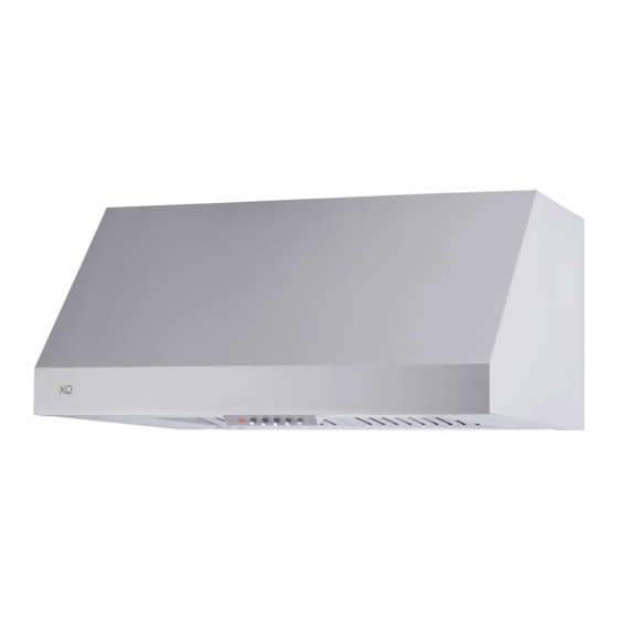
XOT1830S
XOT1836S
Advertisement
Table of Contents

Subscribe to Our Youtube Channel
Related Manuals for Xo XOT1836S


Summary of Contents for Xo XOT1836S
- Page 1 XOT1830S XOT1836S NEED HELP? Call our ventilation experts toll free al 800-966-8300 AVEZ-VOUS BESOIN D’AIDE ? Contactez nos experts au numéro gratuit 800-966-8300 ¿NECESITA AYUDA? Póngase en contacto con nuestros expertos a través del número gratis 800-966-8300 RANGE HOOD - User instructions HOTTE DE CUISINE - Notice d’utilisation...
- Page 2 The warranty is extended to the original purchaser for products purchased for ordinary home use in North America. Should you require service for your XO product call a product service specialist at 800.966.8300 What is not covered Improper Installation.
-
Page 3: Important Safety Instructions
ENGLISH IMPORTANT SAFETY INSTRUCTIONS FOR RESIDENTIAL USE ONLY READ AND SAVE THESE INSTRUCTIONS PLEASE READ ENTIRE INSTRUCTIONS BEFORE PROCEEDING. IMPORTANT: Save these Instructions for the Local Electrical Inspectors use. INSTALLER: Please leave these Instructions with this unit for the owner. OWNER: Please retain these instructions for future reference. -
Page 4: Installation Instructions
Crepes Suzette, Cherries Jubilee, Peppercorn Beef Flambè ). C. Clean ventilating fans frequently. Grease should not be allowed to accumulate on fan or filter. D. Use proper pan size. Always use cookware appropriate for the size of the surface element. E. - Page 5 D. Ducted fans must always be vented to the outdoors. E. This unit must be grounded. WARNING - TO REDUCE THE RISK OF FIRE, USE ONLY METAL DUCTWORK. WARNING - UNDER CERTAIN CIRCUMSTANCES DOMESTIC APPLIANCES MAY BE DAN- GEROUS. A. Do not check filters with hood working. B.
-
Page 6: Duct Fittings
DUCT FITTINGS: Equivalent Total Duct Quantity Dimensions: Number Equivalent This Hood Must Use an Piece: Used: Length*: Length: 6" Round Duct. It Can Transition to 3-1/4" x 10" 1 ft. (per foot Round, straight lenhgth) or 3-1/4" x 12" Duct. 3-1/4"... -
Page 7: Install The Ductwork
WARNING FIRE HAZARD NEVER exhaust air or terminate duct work into spaces between walls, crawl spaces, ceiling, attics or garages. All exhaust must be ducted to the outside, unless using the recirculating option. Use single wall rigid Metal ductwork only. Fasten all connections with sheet metal screws and tape all joints w/ certified Silver Tape or Duct Tape. - Page 8 PRODUCT DIMENSIONS AND CLEARANCE XOT1830S - XOT1836S: › Front of hood › Side of hood 12" 10" 1-13/16" 3-1/4" › Top of hood › Mounting height and clearance: 30" - 36" Min 27" - Max 32" 36" - 8 -...
- Page 9 INSTALLATION INSTRUCTIONS INSTALLATION - VENTED TO THE OUTSIDE 1. ATTENTION! - Before carrying out assembly operations, open the packaging, take the hood and place it on a comfortable surface. - Remove the anti-grease filter/s (Fig.1A). A - If hood installation is used with the air outlet Fig.1B or Fig.1C, the wires set-up in the relevant fairleads must be released by pulling the lever outwards, as indicated in figure 2 - phase 1-2.
- Page 10 lowing the steps in reverse (Fig.2). In this way it will be easier to manoeuvre the unit. - If the appliance id to be mounted in DUCTING version, prepare the air evacuation hole. - It is recommended to use an air evacuation pipe with the same diameter as the air outlet flange.
- Page 11 Attention! This product envisions the air evacuation hole available in 2 different positions, which can be used according to your requirements; 1 – in the upper part of the hood Fig.3A. 2 – in the rear part of the hood Fig.3B. - The air evacuation flange is supplied with the rectangular shape X and circular shape Y (Fig.3).
- Page 12 upper part of the hood (Fig.4A): This product is supplied with the air outlet in the upper part and the electric connection box positioned in the rear part of the hood, as indicated in figure 4B (see paragraph: connection to the electric power supply). - If a rectangular air outlet pipe is used E, the hood is already set-up (Fig.4A.1).
- Page 13 rear part of the hood (Fig.5A): - If your requirements envision the use of the air outlet in the rear part of the hood (carry out all phases shown in figure 5B), remove the screws I (Fig.5A.1) that fix the motor bracket Y and turn the entire motor unit and position it as indicated in Fig.5A.2.
-
Page 14: Power Supply
POWER SUPPLY: IMPORTANT – (Please read carefully) WARNING: FOR PERSONAL SAFETY, THIS APPLIANCE MUST BE PROPERLY GROUNDED. Remove house fuse or open circuit breaker before beginning installation. Do not use an extension cord or adapter plug with this appliance. Follow National electrical codes or prevailing local codes and ordinances. -
Page 15: Connect Electrical
2. CONNECT ELECTRICAL: For connection to the power supply refer to the following Fig.6: 1. Break and remove the small circular metal sheet positioned in the rear part of the hood, with the aid of a flat screw driver Fig.6.1. 2. - Page 16 OPTIONAL: the electric power supply box can be removed and fixed in the position indicated in Fig.7A. WARNING - TO REDUCE THE RISK OF FIRE, ELECTRIC SHOCK, OR INJURY TO PER- SONS, OBSERVE THE FOLLOWING Before connecting the appliance to the power supply network, the electric plant box must be positioned in the seat.
- Page 17 The appliance must be installed at a minimum height of 27" from an electric cooker stove, or 32" from gas or combined cooker stoves. If a connection ductwork composed of two parts is used, the upper part must be placed outside the lower part. Do not connect the range hood exhaust duct air to the same duct air used to exhaust hot air or fumes from other appliances other than electrical.
- Page 18 2 different ways: - Mounting the hood in the lower part of the shelf: 1 type installation Fig.8. - Mounting the hood on the wall: 2 type installation Fig.8. Fig.8 - 18 -...
- Page 19 - Check that the screws used that are not supplied with the product are suitable for the type of object. - Position the fixing template on the lower part of the shelf (Fig.9B), (considering the minimum distance from the cooker top). - Make 6 holes in the shelf respecting the measurements indicated(Fig.9C).
- Page 20 30" 36" 12" 12" 3-1/4" 10" 1-13/16" 1-13/16" 22" 22" 30" 29-15/16" 2" 2" 9/16" 9/16" 6-1/16" 6-1/16" 36" 35-15/16" 2" 2" 9/16" 9/16" 3" 3" Fig.9 - 20 -...
- Page 21 Position the fixing template on the wall (Fig.10B), (considering the minimum distance from the cooker top). - Make 4 holes respecting the measurement indicated in the figures (Fig.10C). - Fix the 2 upper screws A without tightening them completely along with the plugs. - Hang the hood on the wall, aligning it in a horizontal position and tighten/fasten the 2 screws A.
- Page 22 30" 36" 12" 12" 3-1/4" 1-13/16" 1-13/16" 10" 22" 22" 30" 29-15/16" 2" 2" 9/16" 9/16" 6-1/16" 6-1/16" 36" 35-15/16" 2" 2" 9/16" 9/16" 3" 3" Fig.10 - 22 -...
- Page 23 DUCTLESS RECIRCULATING OPTION: 30" 36" CARBON FILTER KIT XORFK07 (30") - XORFK08 (36"): The kit includes an air diverter A, 7 screws B and 2 round filters C. Fig.1: Take the rectangular shape X and fasten it to the hood using the 7 screws. To con- vert this model from the sunction to the filtering version, it is not necessary to use the rectangular shape X.
- Page 24 Fig.2: Remove the aluminum panels by pulling the lever 1 out and pushing downwards Fig.3: Take the bracket A and fasten it to the hood using the 7 screws B (provided). Take the 2 round filters C and apply them onto the bracket as shown in the figure. - 24 -...
- Page 25 Fig.4: The filters C must be applied to the suction unit inside the hood, centering them inside of it and turning them 90° until they snap into place. Fig.5: Put the aluminum panels back in place (Fig.2). - 25 -...
- Page 26 following controls: A = LIGHT B = OFF C = SPEED I D = SPEED II E = SPEED III G = MOTOR WORKING indicator. - 26 -...
-
Page 27: Maintenance
MAINTENANCE We recommend that the cooker hood is switched on before any food is cooked. We also recommend that the appliance is left running for 15 minutes after the food is cooked, in order to thoroughly eliminate all contaminated air. The effective perfor- mance of the cooker hood depends on constant maintenance;... - Page 28 - DO NOT use ordinary steel wool or steel brushes. Small bits of steel may adhere to the surface causing rust. - DO NOT allow salt solutions, disinfectants, bleaches, or cleaning compounds to remain in contact with stainless steel for extended periods. Many of these compounds contain chemicals with may be harmful.
- Page 29 In order to replace the dichroic lamps, carefully remove the lamp from the lamp holder with the help of a small flat screw- driver or a similar tool. PLEASE NOTE! In doing this operation, please take care not to scratch the hood. Replace the bulbs with new ones of the same type.
- Page 30 XOT1830S - XOT1836S: - 30 -...
-
Page 31: Options And Accessories
OPTIONS AND ACCESSORIES: Model XORFK07 (30") - XORFK08 (36") Ductless Recirculating Filter Kit. Buffle filters - 31 -... - Page 32 OPTIONS AND ACCESSORIES: Model XORFK07 (30") - XORFK08 (36") Ductless Recirculating Filter Kit. 30" 36" - 32 -...
- Page 33 XOT Spec Sheet Model: XOT1830S - XOT1836S Sizes: 30" - 36" Features and Benefits: - 600 CFM high velocity blower optimally removes Smoke, Grease and Odors. - 3 speed push button controls. - Two 50W Halogen Lights - Provide brilliant illumination over the cooking surface.
Need help?
Do you have a question about the XOT1836S and is the answer not in the manual?
Questions and answers