Table of Contents
Advertisement
Quick Links
IMPORTANT SAFETY INFORMATION: Always read this manual first before attempting to service this
fireplace. For your safety, always comply with all warnings and safety instructions contained in this
manual to prevent personal injury or property damage.
Manual de servicio
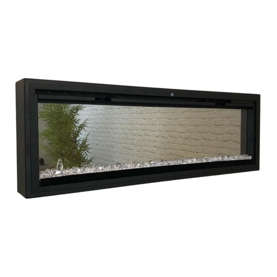
NIGHT13
NIGHT19
NIGHT25
6909630100
6909690100
6909700100
Advertisement
Table of Contents

Subscribe to Our Youtube Channel
Related Manuals for Faber NIGHT 13


Summary of Contents for Faber NIGHT 13
- Page 1 Manual de servicio NIGHT13 6909630100 NIGHT19 6909690100 NIGHT25 6909700100 IMPORTANT SAFETY INFORMATION: Always read this manual first before attempting to service this fireplace. For your safety, always comply with all warnings and safety instructions contained in this manual to prevent personal injury or property damage.
-
Page 2: Table Of Contents
Exploded Parts Diagram NIGHT 13- . . . . . . . . . . . . . . . . . . -
Page 3: Operation
OPERATION Flame Effects Turns the Flame Effect On and Off. Figure 1 → Activated by pressing the button on the remote. Heat ON/OFF Turns the heater On and Off. → Activated by pressing the button on the remote or the unit. -
Page 4: Additional Key Combinations
→ Activated and adjusted by repeatedly pressing the cor- Figure 2 responding button on the remote. • Indicated by the heater running at full heat, for a user set amount of time, to quickly heat up a cold room/space. The Heat Boost can be set for a maximum of 20 minutes, in 5 minute increments. -
Page 5: Maintenance
MAINTENANCE WARNING: Disconnect power and allow heater to cool before attempting any maintenance or cleaning to reduce the risk of fire, electric shock or damage to persons. NOTE: The fireplace should not be operated with an accumulation of dust or dirt on or in the unit, as this can cause a build up of heat and eventual damage. -
Page 6: Exploded Parts Diagram Night 13
EXPLODED PARTS DIAGRAM - NIGHT 13 Replacement Parts List - NIGHT 13 1. Heater Assembly (with cutouts) ..2203720100RP 12. 8-Light LED Flame Assembly ..3001670200RP 2. Remote Control ....3001250100RP 13. -
Page 7: Exploded Parts Diagram Night 19
EXPLODED PARTS DIAGRAM - NIGHT 19 LED Configuration Flame LED’s (white) Flame Base (colour) Media (colour) Replacement Parts List - NIGHT 19 1. Heater Assembly (with cutouts) ..2203720100RP 12. 8-Light LED Flame Assembly (2) ..3001670200RP 2. -
Page 8: Exploded Parts Diagram Night 25
EXPLODED PARTS DIAGRAM - NIGHT 25 LED Configuration Flame LED’s (white) Flame Base (colour) Media (colour) Replacement Parts List - NIGHT 25 1. Heater Assembly (with cutouts) ..2203720100RP 11. 6-Light LED Flame Assembly (5) ..3001670100RP 2. -
Page 9: Wiring Diagrams
WIRING DIAGRAMS NIGHT 13 CERAMIC ELEMENT MAIN CONTROL BOARD THERMAL CUTOUTS THERMISTOR POWER ADAPTER FLICKER MOTOR FLAME LED ASSEMBLY MEDIA LED ASSEMBLY MEDIA LED ASSEMBLY NIGHT 19 NIGHT 25 CERAMIC ELEMENT MAIN CONTROL BOARD THERMAL CUTOUTS THERMISTOR POWER ADAPTER FLICKER MOTOR... -
Page 10: Preparation For Service
NIGHT 13 50.31 in [1278 mm] Figure 3 NIGHT 19 74.31 in [1887 mm NIGHT 25 100.31 in [2548 mm] 4.34 in. NIGHT 13 51.41 in [1306 mm] 110 mm NIGHT 19 75.41 in [1941 mm] NIGHT 25 101.41 in [2576 mm] 5.79 in. -
Page 11: Main Control Board Replacement
(Fig- Figure 6 ure 5) NIGHT 13 7. Gently lift the partially reflective glass out of the unit and set it aside in a safe place. CAUTION: Partially Reflective Glass is not tempered. -
Page 12: Capacative Controls And Display Replacement
2. Remove the screws that secure the holding bracket at least 10 minutes for lights and heating elements to cool and power supply to the unit. off to avoid accidental burning of skin. 3. Trace the wires to the main control board and discon- Tools required: Phillips head screwdriver nect. -
Page 13: Flicker Assembly Replacement
FLICKER ASSEMBLY REPLACEMENT unit. 7. Remove the 2 screws holding the flicker motor to the WARNING: Disconnect power before attempting any mounting bracket. Gently pull the motor away from the maintenance or cleaning to reduce the risk of electric flicker rod. shock or damage to persons. -
Page 14: Blower/Fan Replacement
as prior to the service. Figure 9 Retaining 6. Reassemble in the reverse order as above. Bracket BLOWER/FAN REPLACEMENT WARNING: Disconnect power before attempting any maintenance or cleaning to reduce the risk of electric shock or damage to persons. CAUTION: If unit was operating prior to servicing allow at least 10 minutes for lights and heating elements to cool off to avoid accidental burning of skin. -
Page 15: Troubleshooting Guide
TROUBLESHOOTING GUIDE PROBLEM CAUSE SOLUTION General Circuit breaker trips or fuse blows Short in unit wiring. Trace wiring in unit. when unit is turned on Improper circuit current rating Additional appliances may exceed the current rating of the circuit breaker or fuse. Plug unit into another outlet or install unit on a dedicated 15 amp circuit. - Page 16 PROBLEM CAUSE SOLUTION Heater Heater is not turning on, but flame Improper operation Refer to Operation Section effect is still functioning Loose wiring Trace wiring in unit Defective main control board Replace the main control board Defective Heating Element Replace Heating Element Heater is turning off after a couple Improper operation Refer to Operation Section...
Need help?
Do you have a question about the NIGHT 13 and is the answer not in the manual?
Questions and answers