Table of Contents
Advertisement
Quick Links
Advertisement
Table of Contents

Related Manuals for LTS LTH-D301GY-WIFI-2


Summary of Contents for LTS LTH-D301GY-WIFI-2
- Page 1 Network Indoor Station Installation Guide...
- Page 2 Network Indoor Station Installation Guide Symbol Conventions The symbols that may be found in this document are defined as follows. Symbol Description Indicates a hazardous situation which, if not avoided, will or could Danger result in death or serious injury. Indicates a potentially hazardous situation which, if not avoided, Caution could result in equipment damage, data loss, performance...
-
Page 3: Table Of Contents
Network Indoor Station Installation Guide Contents Chapter 1 Appearance ........................ 1 Chapter 2 Terminal and Wiring Description ................3 2.1 Terminal Description ......................3 2.2 Wiring Description ......................... 3 Chapter 3 Installation ......................... 5 3.1 Wall Mounting Plate ......................5 3.2 Wall Mounting with Junction Box .................. -
Page 4: Chapter 1 Appearance
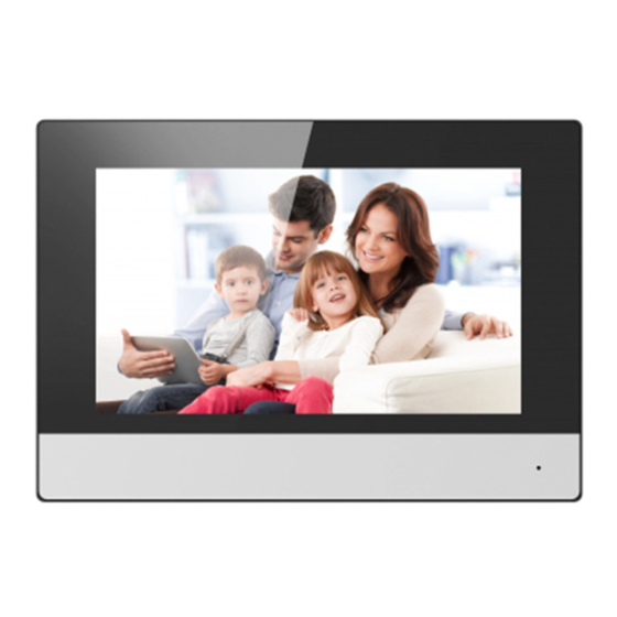
Network Indoor Station Installation Guide Chapter 1 Appearance Front Panel Figure 1-1 Front Panel Table 1-1 Description Description Display Screen Microphone... - Page 5 Network Indoor Station Installation Guide Rear Panel Figure 1-2 Rear Panel Table 1-2 Description Description Debugging Port Network Interface Loudspeaker TF Card Slot Alarm Terminal Reserved Network Interface and Power Supply Note The debugging port is used for debugging only.
-
Page 6: Chapter 2 Terminal And Wiring Description
Network Indoor Station Installation Guide Chapter 2 Terminal and Wiring Description 2.1 Terminal Description There are 20 pins in the terminal on the rear panel of the indoor station: 2 RS-485 pins, 5 reserved pins, 4 relay output pins, 8 alarm input pins, and 1 GND pin. Figure 2-1 Terminal Description 2.2 Wiring Description Wire the devices with power supply cables as picture shown below. - Page 7 Network Indoor Station Installation Guide Figure 2-2 Wiring Description...
-
Page 8: Chapter 3 Installation
Network Indoor Station Installation Guide Chapter 3 Installation Indoor station supports wall mounting. 3.1 Wall Mounting Plate The wall mounting plate and the junction box are required to install the indoor station onto the wall. The dimension of junction box should be 75 mm (width) × 75 mm (length) × 50 mm (depth). The dimension of wall mounting plate is shown. - Page 9 Network Indoor Station Installation Guide ● Check the product specification for the installation environment. Steps 1. Chisel a hole in the wall. The size of the hole should be 76 mm (width) × 76 mm (length) × 50 mm (depth). 2.
Need help?
Do you have a question about the LTH-D301GY-WIFI-2 and is the answer not in the manual?
Questions and answers