Table of Contents
Advertisement
Quick Links
Advertisement
Table of Contents

Related Manuals for CG Emotron VS30401P3


Summary of Contents for CG Emotron VS30401P3
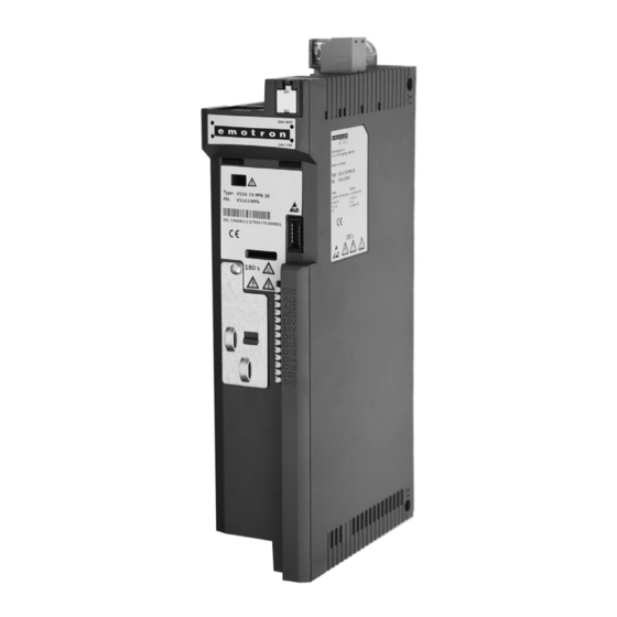
- Page 1 Emotron VS10 / VS30 AC drive 0.25 … 2.2 kW Mounting and switch on instruction...
- Page 2 This page intentionally left blank!
-
Page 3: Table Of Contents
Contents Contents 1 General information ..........................4 First read, then start ........................4 Notations and conventions ......................4 2 Safety instructions ..........................5 Basic safety measures ......................... 5 Residual hazards ......................... 6 Application as directed ....................... 6 3 Product description ........................... - Page 4 General information First read, then start General information First read, then start WARNING! Read this documentation thoroughly before carrying out the installation and commissioning. ▶ Please observe the safety instructions! Information and tools with regard to the Emotron products can be found on the Internet: http://www.emotron.com/ services-support/file-archive/ Notations and conventions 1.2.1...
-
Page 5: General Information
Safety instructions Basic safety measures Safety instructions Basic safety measures Disregarding the following basic safety measures may lead to severe personal injury and damage to material assets! The product • must only be used as directed. • must never be commissioned if they display signs of damage. •... -
Page 6: Safety Instructions
Safety instructions Residual hazards Residual hazards The user must take the residual hazards mentioned into consideration in the risk assessment for his/her machine/system. If the above is disregarded, this can lead to severe injuries to persons and damage to material assets! Product Observe the warning labels on the product! Icon... -
Page 7: Residual Hazards
Product description Product description Earth/ground connection (PE) Relay output X9 Mains voltage connection X100 IT screw Network X2xx CANopen/Modbus(Option) Memory module X20 Shield connection Inverter status LEDs CANopen/Modbus Toggle switch CANopen/Modbus Interface X16 Diagnostic Module Control terminals X3 Shield connection Basic I/O Control connection IT screw... -
Page 8: Product Description
Mounting Important notes Mounting Important notes DANGER! Dangerous electrical voltage Possible consequence: death or severe injuries ▶ All works on the inverter must only be carried out in the deenergised state. ▶ After switching off the mains voltage, wait for at least 3 minutes before you start working. -
Page 9: Mounting
Mounting Mechanical installation Mechanical installation Dimensions VS10/VS30 - 0.25 kW ... 0.37 kW All dimensions in mm... -
Page 10: Mechanical Installation
Mounting Mechanical installation Dimensions VS10/VS30 - 0.55 kW ... 0.75 kW All dimensions in mm... - Page 11 Mounting Mechanical installation Dimensions VS30 - 1.1 kW ... 2.2 kW All dimensions in mm...
- Page 12 Mounting Electrical installation 4.3.1 1-phase mains connection 230/240 V The wiring diagram is valid for I5xAExxxB inverters. 3/N/PE 3/N/PE 2/N/PE AC 400 V AC 208 V ... 240 V AC 208 V ... 240 V … … 1/N/PE 2/PE 2/PE AC 170 V ...
-
Page 13: Electrical Installation
Mounting Electrical installation Connection to the 230 V system 4.3.1.1 Fusing and terminal data Inverter VS30401P3 VS30401P8 VS30402P4 VS30403P2 VS30403P9 VS30405P6 VS30401P3 Cable installation in EN 60204-1 compliance with Laying system Operation without mains choke Fuse Characteristic gG/gL or gRL Max. -
Page 14: 1-Phase Mains Connection 230/240 V
Mounting Electrical installation Connection to the 230 V system 4.3.2- 1/3-phase mains connection 230/240V The wiring diagram is valid for Emotron VS10/VS30 inverters. Emotron VS10/VS30 inverters do not have an integrated EMC filter in the AC mains supply. In order to comply with the EMC requirements according to EN 61800−3, an external EMC filter according to IEC EN 60939 has to be used. - Page 15 Mounting Electrical installation Connection to the 230 V system 4.3.2.1 Fusing and terminal data Inverter VS30401P3 VS30401P8 VS30402P4 VS30403P2 VS30403P9 VS30405P6 VS30401P3 Cable installation in EN 60204-1 compliance with Laying system Operation without mains choke Fuse Characteristic gG/gL or gRL Max.
-
Page 16: 4.3.2.1 Fusing And Terminal Data
Mounting Electrical installation Connection to the 230 V system 4.3.3 3-phase mains connection 400 V The wiring diagram is valid for I5xAExxxF inverters. 3/N/PE AC 400 V … 3/PE AC 340 V ... 528 V 45 Hz ... 65 Hz CAN open/Modbus Modbus AC 240 V... -
Page 17: 1/3-Phase Mains Connection 230/240 V
Mounting Electrical installation Connection to the 400 V system 4.3.3.1 Fusing and terminal datas Inverter VS30401P3 VS30401P8 VS30402P4 VS30403P2 VS30403P9 VS30405P6 Cable installation in EN 60204-1 compliance with Laying system Operation without mains choke Fuse Characteristic gG/gL or gRL Max. rated current Circuit breaker Characteristic Max. - Page 18 Mounting Electrical installation Connection to the IT system 4.3.4 Connection to the IT system NOTICE! Internal components have earth/ground potential if the IT screws are not removed. Consequence: the monitoring functions of the IT system respond. ▶ Before connection to an IT system be absolutely sure to remove the IT screws. VS10231P7, VS10232P4, VS10233P2, VS10234P2, VS10236P0, VS10237P0, VS10239P6,...
-
Page 19: Fusing And Terminal Data
Mounting Electrical installation CANopen/Modbus connection 4.3.5 CANopen/Modbus connection 4.3.5.1 Connection plan X216 X216 X216 X216 Fig. 3: Wiring example: CANopen or Modbus network 4.3.5.2 Terminal data Terminal description CANopen/Modbus Connection X216 Connection type Spring terminal Min. cable cross-section mm² Max. cable cross-section mm²... -
Page 20: 3-Phase Mains Connection 480 V
Commissioning Important notes Commissioning Important notes WARNING! Incorrect settings during commissioning may cause unexpected and dangerous motor and system movements. Possible consequence: death, severe injuries or damage to property ▶ Clear hazardous area. ▶ Observe safety instructions and safety clearances. Before initial switch-on Prevent injury to persons and damage to property. - Page 21 Commissioning Initial switch-on / functional test with terminal control Initial switch-on / functional test with terminal control Target: achieve rotation of the motor connected to the inverter as quickly as possible. Requirements: • The connected motor matches the inverter in terms of power. •...
-
Page 22: Fusing And Terminal Data
Commissioning Initial switch-on / functional test with terminal control Carrying out the functional test 1. Start drive: 1. Start inverter: X3/DI1 = HIGH. 2. Activate preset frequency setpoint 1 (20 Hz) as speed setpoint: X3/DI4 = HIGH. The drive rotates with 20 Hz. 3. -
Page 23: Canopen/Modbus
Technical data Standards and operating conditions Technical data Standards and operating conditions Conformities 2014/35/EU Low-Voltage Directive 2014/30/EU EMC Directive (reference: CE-typical drive system) TR TC 004/2011 Eurasian conformity: Safety of low voltage equipment TP TC 020/2011 Eurasian conformity: Electromagnetic compatibility of technical means RoHS 2 2011/65/EU... -
Page 24: Commissioning
Technical data Standards and operating conditions dimensioning for rated power. Rsce ≥ 120 is to be met. Requirements to the shielded motor cable Capacitance per unit length C-core-core/C-core-shield < 75/150 ≤ 2,5 mm² / AWG 14 pF/m C-core-core/C-core-shield < 150/300 ≥... -
Page 25: Initial Switch-On / Functional Test With Terminal Control
Technical data Rated data Connection to the 230 V system 1-phase mains connection 230/240 V 6.2.1 Rated data The output currents apply to these operating conditions: • At a switching frequency of 2 kHz or 4 kHz: Max. ambient temperature 45°C. •... - Page 26 1/3-phase mains connection 230/240 V Rated data 6.3 1/3-phase mains connection 230/240 V Emotron VS10/30 inverters do not have an integrated EMC filter in the AC mains supply. In order to comply with the EMC requirements according to EN 61800−3, an external EMC filter according to IEC EN 60939 has to be used.
-
Page 27: Technical Data
Technical data 3-phase mains connection 400 V Rated data 3-phase mains connection 400 V 6.4.1 Rated data The output currents apply to these operating conditions: • At a switching frequency of 2 kHz or 4 kHz: Max. ambient temperature 45°C. •... - Page 28 ©03/2016 | 13504491| 2.0 / 01-6210-01R3 CG DRIVES & AUTOMATION Mörsaregatan 12, Box 222 25 SE- 250 24 Helsingborg, Sweden +46 42 16 99 00 Info: info.se@cgglobal.com Order: order.se@cgglobal.com...
Need help?
Do you have a question about the Emotron VS30401P3 and is the answer not in the manual?
Questions and answers