Table of Contents
Advertisement
Quick Links
Advertisement
Table of Contents

Related Manuals for CG Emotron DSV15


Summary of Contents for CG Emotron DSV15
- Page 1 Emotron DSV15/35 AC drive 0.25 … 2.2 kW Mounting and switch on instruction...
- Page 2 This page intentionally left blank!
-
Page 3: Table Of Contents
Contents Contents 1 General information 1.1 Read first, then start 1.2 Notations and conventions 1.2.1 Product code 2 Safety instructions 2.1 Basic safety measures 2.2 Residual hazards 2.3 Application as directed 3 Product description 4 Mounting 4.1 Important notes 4.2 Mechanical installation 4.3 Electrical installation 4.3.1 1-phase mains connection 230/240 V... -
Page 4: General Information
General information Read first, then start General information Read first, then start WARNING! Read this documentation thoroughly before carrying out the installation and commissioning. ▶ Please observe the safety instructions! Information and tools with regard to the Emotron products can be found on the Internet: http://www.emotron.com à... -
Page 5: Safety Instructions
The procedural notes and circuit details described in this document are only proposals. It is up to the user to check whether they can be adapted to the particular applications. CG D&A does not take any responsibility for the suitability of the procedures and circuit proposals described. -
Page 6: Residual Hazards
Safety instructions Residual hazards Residual hazards The user must take the residual hazards mentioned into consideration in the risk assessment for his/her machine/system. If the above is disregarded, this can lead to severe injuries to persons and damage to material assets! Product Observe the warning labels on the product! Icon... -
Page 7: Product Description
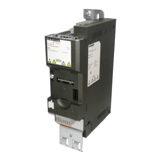
Product description Product description... -
Page 8: Mounting
Mounting Important notes Mounting Important notes DANGER! Dangerous electrical voltage Possible consequence: death or severe injuries ▶ All works on the inverter must only be carried out in the deenergised state. ▶ After switching off the mains voltage, wait for at least 3 minutes before you start working. -
Page 9: Mechanical Installation
Mounting Mechanical installation Mechanical installation Dimensions 0,25 kW ... 0,37 kW All dimensions in mm... - Page 10 Mounting Mechanical installation Dimensions 0,55 kW ... 0,75 kW All dimensions in mm...
- Page 11 Mounting Mechanical installation Dimensions 1,1 kW ... 2,2 kW All dimensions in mm...
-
Page 12: Electrical Installation
Mounting Electrical installation 1-phase mains connection 230/240 V Electrical installation 4.3.1 1-phase mains connection 230/240 V The wiring diagram is valid for Emotron DSV15-35 inverters. 3/N/PE 3/N/PE 2/N/PE AC 400 V AC 208 V ... 240 V AC 208 V ... 240 V …... -
Page 13: Fusing And Terminal Data
Mounting Electrical installation 1-phase mains connection 230/240 V 4.3.1.1 Fusing and terminal data Inverter DSV15231P7 DSV15232P4 DSV15233P2 DSV15234P2 DSV15236P0 DSV15237P0 DSV15239P6 Cable installation in EN 60204-1 compliance with Laying system Operation without mains choke Fuse Characteristic gG/gL or gRL Max. rated current Circuit breaker Characteristic Max. -
Page 14: 3-Phase Mains Connection 400 V
Mounting Electrical installation 3-phase mains connection 400 V 4.3.2 3-phase mains connection 400 V The wiring diagram is valid for Emotron DSV 35 inverters. 3/N/PE AC 400 V … 3/PE AC 340 V ... 528 V 45 Hz ... 65 Hz CAN open Modbus PROFIBUS... -
Page 15: Fusing And Terminal Data
Mounting Electrical installation 3-phase mains connection 400 V 4.3.2.1 Fusing and terminal data Inverter DSV35401P3 DSV35401P8 DSV35402P4 DSV35403P2 DSV35403P9 DSV35407P3 Cable installation in EN 60204-1 compliance with Laying system Operation without mains choke Fuse Characteristic gG/gL or gRL Max. rated current Circuit breaker Characteristic Max. -
Page 16: Connection To The It System
Mounting Electrical installation Connection to the IT system 4.3.3 Connection to the IT system NOTICE! Internal components have earth/ground potential if the IT screws are not removed. Consequence: the monitoring functions of the IT system respond. ▶ Before connection to an IT system be absolutely sure to remove the IT screws. DSV15231P7 DSV15232P4 DSV15233P2... -
Page 17: Canopen
All other combinations Value from parameter (500 kbps) Printed in bold = CG setting The network must be terminated with a 120 Ω resistor at the physically first and last node. Set the "R" switch to ON at these nodes. -
Page 18: Modbus
Node address = 16 + 4 + 2 + 1 = 23 Node address > 247: value from parameter Printed in bold = CG setting The network must be terminated with a 120 Ω resistor at the physically first and last node. -
Page 19: Profibus
Station address = 16 + 4 + 2 + 1 = 23 Do not set station address = 126 and station address = 127. These station addresses are invalid. Printed in bold = CG setting The network must be terminated with a resistor at the physically first and last node. -
Page 20: Ethercat
Mounting Electrical installation EtherCAT 4.3.7 EtherCAT Typical topologies Line OUT IN Master Slave Device Bus-related information Name EtherCAT Communication medium Ethernet 100 Mbps, full duplex Connection of the inverter to an EtherCAT network Connection system RJ45 Status display 2 LEDs Connection designation In: X246 Out: X247... -
Page 21: Ethernet/Ip
Mounting Electrical installation EtherNet/IP 4.3.8 EtherNet/I P Typical topologies Line Tree Ring Scanner Adapter Bus-related information Name EtherNet/IP Communication medium Ethernet 10 Mbps, 100 Mbps, half duplex, full duplex Connection of the inverter to an EtherNet/IP network Connection system RJ45 Status display 2 LEDs Connection designation... -
Page 22: Profinet
Mounting Electrical installation PROFINET 4.3.9 PROFINET Typical topologies Line Tree Ring I/O controller Switch SCALANCE (MRP capable) I/O device Redundant domain Bus-related information Name PROFINET RT Communication medium Ethernet 100 Mbps, full duplex Connection of the inverter to a PROFINET network Connection system RJ45 Status display... -
Page 23: Connection Of The Safety Module
Mounting Electrical installation Connection of the safety module 4.3.10 Connection of the safety module 4.3.10.1 Important notes DANGER! Improper installation of the safety engineering system can cause an uncontrolled starting action of the drives. Possible consequences: Death or severe injuries ▶... -
Page 24: Connection Plan
Mounting Electrical installation Connection of the safety module 4.3.10.2 Connection plan Passive sensors Active sensors safety switching device active sensor - example lightgrid passive sensor 4.3.10.3 Terminal data Terminal description Safety STO Connection Connection type Screw terminal Min. cable cross-section mm²... -
Page 25: Commissioning
Commissioning Important notes Commissioning Important notes WARNING! Incorrect settings during commissioning may cause unexpected and dangerous motor and system movements. Possible consequence: death, severe injuries or damage to property ▶ Clear hazardous area. ▶ Observe safety instructions and safety clearances. Before initial switch-on Prevent injury to persons and damage to property. -
Page 26: Initial Switch-On / Functional Test With Terminal Control
Commissioning Initial switch-on / functional test with terminal control Initial switch-on / functional test with terminal control Target: achieve rotation of the motor connected to the inverter as quickly as possible. Requirements: • The connected motor matches the inverter in terms of power. •... - Page 27 Commissioning Initial switch-on / functional test with terminal control Carrying out the functional test 1. Start drive: 1. Start inverter: X3/DI1 = HIGH. a) If the inverter is equipped with an integrated safety system: X1/SIA = HIGH and X1/SIB = HIGH. 2.
- Page 28 Technical data Standards and operating conditions Technical data Standards and operating conditions Conformities 2014/35/EU Low-Voltage Directive 2014/30/EU EMC Directive (reference: CE-typical drive system) TR TC 004/2011 Eurasian conformity: safety of low voltage equipment TP TC 020/2011 Eurasian conformity: electromagnetic compatibility of technical means RoHS 2 2011/65/EU...
-
Page 29: Technical Data
Technical data Standards and operating conditions Mains current > 16 A: with mains EN 61000-3-12 RSCE: short-circuit power ratio at the connection point choke or mains filter, with of the machine/plant to the public network. dimensioning for rated power. Rsce ≥ 120 is to be met. -
Page 30: 1-Phase Mains Connection 230/240 V
Technical data 1-phase mains connection 230/240 V Rated data 1-phase mains connection 230/240 V 6.2.1 Rated data The output currents apply to these operating conditions: • At a switching frequency of 2 kHz or 4 kHz: Max. ambient temperature 45°C. •... - Page 31 Technical data 3-phase mains connection 400 V Rated data 3-phase mains connection 400 V 6.3.1 Rated data The output currents apply to these operating conditions: • At a switching frequency of 2 kHz or 4 kHz: Max. ambient temperature 45°C. •...
- Page 32 © 02/2016 | 13500560 | 3.0 / 01-6229-01R1 CG Drives& Automation Sweden AB Mörsaregatan 12 Box 222 25 SE-250 24 HELSlNGBORG Sweden Tel +46 42 169900 info@cgglobal.com www.emotron.com...
Need help?
Do you have a question about the Emotron DSV15 and is the answer not in the manual?
Questions and answers