CG Emotron VS30 Series Mounting And Switch On Instruction
Ac drive
Hide thumbs
Also See for Emotron VS30 Series:
- Mounting instructions (8 pages) ,
- Mounting and switch on instruction (28 pages)

Related Manuals for CG Emotron VS30 Series


Summary of Contents for CG Emotron VS30 Series
- Page 1 Emotron VS30 AC drive 4 - 10 hp Use in UL approved systems Mounting and switch on instruction...
- Page 2 This page intentionally left blank!
-
Page 3: Table Of Contents
Contents Contents 1 General information 1.1 First read, then start 1.2 Notations and conventions 1.2.1 Product code 2 Safety instructions 2.1 Basic safety measures 2.2 Residual hazards 2.3 Application as directed 3 Product description 4 Mounting 4.1 Important notes 4.2 Mechanical installation 4.3 Electrical installation 4.3.1 Connection plan... - Page 4 This page is intentionally left blank.
-
Page 5: General Information
General information First read, then start General information Read first, then start WARNING! Read this documentation thoroughly before carrying out the installation and commissioning. ▶ Please observe the safety instructions! Information and tools with regard to the Emotron products can be found on the Internet: http://www.emotron.com/file-archive Notations and conventions 1.2.1... -
Page 6: Safety Instructions
The procedural notes and circuit details described in this document are only proposals. It is up to the user to check whether they can be adapted to the particular applications. CG D&A does not take any responsibility for the suitability of the procedures and circuit proposals described. -
Page 7: Residual Hazards
Safety instructions Residual hazards Residual hazards The user must take the residual hazards mentioned into consideration in the risk assessment for his/her machine/system. If the above is disregarded, this can lead to severe injuries to persons and damage to material assets! Product Observe the warning labels on the product! Description... -
Page 8: Product Description
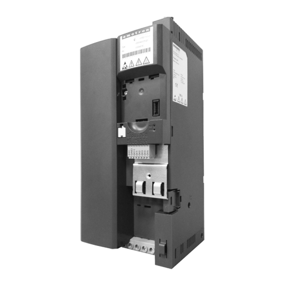
Product description Product description Mains connection X100 PE connection Relay output X9 Network X2xx Option Network status LEDs DIP switch Baud rate and bus adress Interface X16 (CANopen/Modbus) Diagnostic module Inverter status LEDs Memory moodule X20 Control terminals X3 Standard I/O Shield connection Control connections IT screw... -
Page 9: Mounting
Mounting Important notes Mounting Important notes DANGER! Dangerous electrical voltage Possible consequence: death or severe injuries ▶ All works on the inverter must only be carried out in the deenergised state. ▶ After switching off the mains voltage, wait for at least 3 minutes before you start working. -
Page 10: Mechanical Installation
Mounting Mechanical installation Mechanical installation Dimensions 4 ... 7.5 hp All Dimensions in inches... - Page 11 Mounting Mechanical installation Dimensions 10 hp All Dimensions in inches...
-
Page 12: Electrical Installation
Mounting Electrical installation Connection plan Electrical installation 4.3.1 Connection plan Fig. 1: Wiring example Start enable Dashed line = options... - Page 13 Mounting Electrical installation 4.3.1.1 Fusing and terminal data Inverter VS30407P3 VS30409P5 VS3040013 VS3040016 Cable installation in compliance with Operation without mains choke Fuse Characteristic all acc. to UL 248/CC all acc. to UL 248/J, T, R Max. rated current Circuit breaker Characteristic Max.
- Page 14 Mounting Electrical installation Connection to IT system 4.3.2 Connection to the IT system NOTICE! Internal components have earth potential if the IT screws are not removed. Consequence: the monitoring functions of the IT system respond. ▶ Before connection to an IT system be absolutely sure to remove the IT screws. TX10 TX10...
- Page 15 Mounting CANopen 4.3.3 CANopen connection 4.3.3.1 Connection plan X216 X216 X216 X216 Fig. 2: Wiring example: CANopen network 4.3.3.2 Terminal data Terminal description CANopen Connection X216 Connection type Spring terminal Min. cable cross-section mm² Max. cable cross-section mm² Stripping length Tightening torque Required screwdriver 0.4 x 2.5...
- Page 16 Mounting Modbus 4.3.4 Modbus connection 4.3.4.1 Connection plan X216 X216 X216 X216 TB COM TB COM TB COM TB COM Fig. 3: Wiring example: Modbus network 4.3.4.2 Terminal data Terminal description Modbus Connection X216 Connection type Spring terminal Min. cable cross-section mm²...
-
Page 17: Commissioning
Commissioning Important notes Commissioning Important notes WARNING! Incorrect settings during commissioning may cause unexpected and dangerous motor and system movements. Possible consequence: death, severe injuries or damage to material assets ▶ Clear hazardous area. ▶ Observe safety instructions and safety clearances. Before initial switch-on Prevent injury to persons and damage to material assets. -
Page 18: Initial Switch-On / Functional Test
Commissioning Initial switch-on / functional test Initial switch-on / functional test Target: achieve rotation of the motor connected to the inverter as quickly as possible. Requirements: • The connected motor matches the inverter in terms of power. • The parameter settings comply with the delivery status (Emotron setting). 1. - Page 19 Commissioning Initial switch-on / functional test Carrying out the functional test 1. Start drive: 1. Enable inverter: X3/DI1 = HIGH. 2. Activate preset setpoint 1 (20 Hz) as speed setpoint: X3/DI4 = HIGH. The drive rotates with 20 Hz. 3. Optional: activate the function for the reversal of rotation direction. a) X3/DI3 = HIGH.
- Page 20 Technical data Standards and operating conditions Technical data Standards and operating conditions Conformities 2014/35/EU Low-Voltage Directive 2014/30/EU EMC Directive (reference: CE-typical drive system) TR TC 004/2011 Eurasian conformity: Safety of low voltage equipment TP TC 020/2011 Eurasian conformity: Electromagnetic compatibility of technical means RoHS 2 2011/65/EU...
-
Page 21: Technical Data
Technical data Standards and operating conditions Requirements to the shielded motor cable Capacitance per unit length C-core-core/C-core-shield < 75/150 ≤ 2,5 mm² / AWG 14 pF/m C-core-core/C-core-shield < 150/300 ≥ 4 mm² / AWG 12 pF/m Electric strength Uo/U = 0,6/1,0 kV Uo = r.m.s. -
Page 22: Rated Data
Technical data Rated data Connection to the 480 V system Rated data VS30407P3 VS30409P5 VS3040013 VS3040016 Inverter Rated power Mains voltage range 3/PE AC 340 V ... 528 V, 45 Hz ... 65 Hz Rated mains current without mains choke 10.5 14.3 16.6... - Page 24 ©06/2016 | 13506912 | 1.0 / 01-6410-01r1 CG DRIVES & AUTOMATION Mörsaregatan 12, Box 222 25 SE- 250 24 Helsingborg, Sweden +46 42 16 99 00 Info: info.se@cgglobal.com Order: order.se@cgglobal.com...
Need help?
Do you have a question about the Emotron VS30 Series and is the answer not in the manual?
Questions and answers