
Related Manuals for Hoshizaki C101BAHA


Summary of Contents for Hoshizaki C101BAHA
- Page 1 Hoshizaki Hoshizaki America, Inc. Self-Contained Cubelet Models C-101BAH C-101BAH-DS C-101BAH-AD C-101BAH-ADDS SERVICE MANUAL “A Superior Degree of Reliability” www.hoshizaki.com Number: 73195 Issued: 11-7-2013...
- Page 2 Hoshizaki provides this manual primarily to assist qualified service technicians in the service of the appliance. Should the reader have any questions or concerns which have not been satisfactorily addressed, please call, send an e-mail message, or write to the Hoshizaki Technical Support Department for assistance. Phone: 1-800-233-1940; (770) 487-2331 Fax: 1-800-843-1056;...
-
Page 3: Table Of Contents
IMPORTANT This manual should be read carefully before the appliance is serviced. Read the warnings and guidelines contained in this manual carefully as they provide essential information for the continued safe use, service, and maintenance of the appliance. Retain this manual for any further reference that may be necessary. CONTENTS Important Safety Information .................... -
Page 4: Important Safety Information
Important Safety Information Throughout this manual, notices appear to bring your attention to situations which could result in death, serious injury, damage to the appliance, or damage to property. WARNING Indicates a hazardous situation which could result in death or serious injury. - Page 5 WARNING, continued • Do not place fingers or any other objects into the ice discharge opening. • The appliance is not intended for use by persons (including children) with reduced physical, sensory, or mental capabilities, or lack of experience and knowledge, unless they have been given supervision or instruction concerning use of the appliance by a person responsible for their safety.
- Page 6 NOTICE, continued • Keep ventilation openings, in the appliance enclosure or in the built-in structure, clear of obstruction. • Do not place objects on top of the appliance. • The storage bin is for ice use only. Do not store anything else in the storage bin.
-
Page 7: Construction And Water/Refrigeration Circuit Diagram
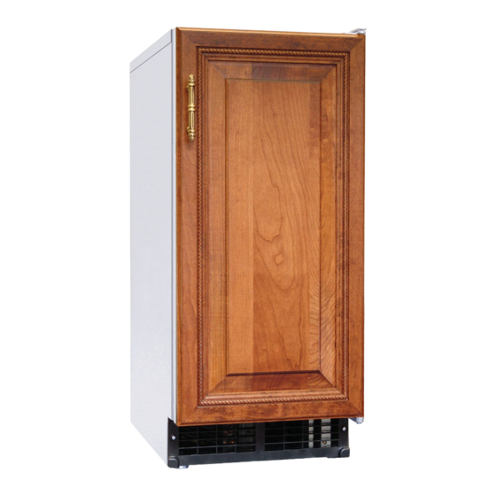
I. Construction and Water/Refrigeration Circuit Diagram A. Construction Top Panel 1. Icemaker Ice Discharge Opening Bin Control Thermostat Bulb Scoop Holder Slope Front Panel Magnet Catch Control Switch Door Front Power Cord Louver C-101BAH-AD Shown Top Panel Inlet Water Valve Evaporator Condensate Drain Pan Evaporator... -
Page 8: Ice Making Assembly
2. Ice Making Assembly Cutter (motionless) Evaporator Flange Seal Bolt Extruding Head and Upper Bearing Auger Gear Motor Cylinder Insulation Mechanical Seal O-Ring Housing and Lower Bearing Socket Head Cap Screw Spline Coupling with Washer Hex Head Bolt with Washer... -
Page 9: Water/Refrigeration Circuit Diagram
3. Water/Refrigeration Circuit Diagram Inlet Water Valve Water Inlet Evaporator Condensate Drain Pan (Drip Pan) Water Level Float Switch Evaporator Water Reservoir Assembly Overflow Hose Evaporator Condensate Gear Drain Pan (Drip Pan) Hose Motor Evaporator Water Supply Hose Drain Valve Drain Valve Drain Hose To Bin Bin Drain Hose... -
Page 10: Sequence Of Operation And Service Diagnosis
II. Sequence of Operation and Service Diagnosis A. Sequence of Operation Flow Chart... -
Page 11: Service Diagnosis
B. Service Diagnosis WARNING • This appliance should be diagnosed and repaired only by qualified service personnel to reduce the risk of death, electric shock, serious injury, or fire. • Risk of electric shock. Use extreme caution and exercise safe electrical practices. •... - Page 12 3) After all of the water has drained, move the control switch to the "OFF" position, then unplug the appliance. 4) Remove the front panel, louver, and upper and lower rear panels. 5) Remove the screws securing the control box, then gently pull out the control box and secure it in a safe position.
- Page 13 GM Diagnosis: Check that GM energizes. If not, check for 115VAC at GM. If 115VAC is not present, check GM external protector on front of control box. If tripped, reset. If it does not reset, replace GM external protector. Once reset, if GM does not energize, check GM windings (internal protector) and GM capacitor.
-
Page 14: Bin Control Check
C. Bin Control Check BC shuts down the icemaker within 10 sec. when ice contacts the thermostatic bulb, regardless of the cycle at activation. NOTICE When the ambient temperature is below 45°F (7°C), BC opens and shuts down the appliance even if the ice storage bin is empty. When BC is set in the prohibited range, the appliance operates continuously even if the ice storage bin is filled with ice. -
Page 15: Float Switch Check And Cleaning
2) Remove the upper rear panel. 3) Remove FS assembly from the reservoir cover. 4) Wipe down FS assembly with a mixture of 1 part Hoshizaki "Scale Away" and 25 parts warm water. Rinse the assembly thoroughly with clean water. - Page 16 6) Rinse FS assembly thoroughly with clean water and replace in its correct position. 7) Replace the upper rear panel in its correct position. 8) Plug the appliance into the electrical outlet, then move the control switch to the "ICE" position to start the automatic icemaking process.
-
Page 17: Optional Drain Pump Hs-5061
E. Optional Drain Pump HS-5061 1. Overview As ice melts, water drains from the storage bin into DP. LFS closes. Nothing happens at this time. UFS closes, DP energizes and pumps out the water. UFS opens, nothing happens at this time. LFS opens, DP de-energizes. If water cannot be pumped out of DP due to a blocked discharge hose, bad check valve, or bad DP motor, water level continues to rise and SFS closes. -
Page 18: Diagnostic Tables
F. Diagnostic Tables 1. No Ice Production No Ice Production - Possible Cause Startup/Fill Cycle 1. Power Supply a) Unplugged, off, blown fuse, or tripped breaker. b) Not within specifications. 2. Optional Drain Pump HS-5061 a) Drain pump connection unplugged or loose. b) Drain pump safety float switch open. - Page 19 Refill 1. Float Switch a) Dirty/sticking. See "II.D. Float Switch Check b) Defective. and Cleaning." 2. Inlet Water Valve a) Screen or orifice clogged. b) Defective. 3. Water Supply a) Water supply off or improper water pressure (7 to 113 PSIG). b) External water filters clogged.
-
Page 20: Controls And Relays
III. Controls and Relays The C-101BAH(-C) utilizes a control switch, time delay relay, water control relay, and compressor relay to control operation. A. Control Switch The control switch has 3 positions, "OFF," "ICE," and "DRAIN." a) "OFF": All components except the optional drain pump are de-energized when the control switch is in the "OFF"... -
Page 21: Refrigeration Circuit And Component Service Information
IV. Refrigeration Circuit and Component Service Information WARNING • This appliance should be diagnosed and repaired only by qualified service personnel to reduce the risk of death, electric shock, serious injury, or fire. • Move the control switch to the "OFF" position, then unplug the appliance from the electrical outlet before servicing. - Page 22 5) Disconnect the gauge manifold hose from the vacuum pump and attach it to a refrigerant service cylinder. Remember to loosen the connection and purge the air from the hose. For the required refrigerant charge, see the nameplate. Hoshizaki recommends only virgin refrigerant or reclaimed refrigerant which meets ARI Standard...
- Page 23 6) A liquid charge is required when charging an R-134a system. Place the service cylinder on the scales; if the service cylinder is not equipped with a dip tube, invert the service cylinder, then place it on the scales. Open the high-side valve on the gauge manifold. 7) Allow the system to charge with liquid until the proper charge weight is met.
-
Page 24: Component Service Information
B. Component Service Information NOTICE • When replacing a component listed below, see the notes to help ensure proper operation. • When replacing evaporator assembly and water circuit components, make sure there are no water leaks after the repair is complete. Component Notes Extruding Head •... - Page 25 Evaporator Assembly Thumbscrew Seal Bolts Spout Inspect for leakage around seal bolts. Tighten (11.1 ft-lb/15 N·m) or replace as necessary. Seal bolts must be replaced once removed because seal material is one-time use only. Cutter If new seal bolts do not have preapplied (motionless) threadlocker, apply Loctite 243 or Packing...
-
Page 26: Upper Bearing Wear Check
1. Upper Bearing Wear Check To ensure that the bearing inside the extruding head does not exceed the wear tolerance of .02", follow the instructions below. 1) Move the control switch to the "OFF" position, then unplug the appliance from the electrical outlet. -
Page 27: Removal And Replacement Of Extruding Head
2. Removal and Replacement of Extruding Head 1) Close the water supply line shut-off valve. 2) Move the control switch to the "DRAIN" position. 3) Allow the water system to drain for 1 minute. 4) Remove all ice from the storage bin. 5) After all of the water has drained, move the control switch to the "OFF"... -
Page 28: Removal And Replacement Of Auger
3. Removal and Replacement of Auger 1) Close the water supply line shut-off valve. 2) Move the control switch to the "DRAIN" position. 3) Allow the water system to drain for 1 minute. 4) After all of the water has drained, move the control switch to the "OFF" position. Unplug the appliance from the electrical outlet. -
Page 29: Removal And Replacement Of Evaporator
4. Removal and Replacement of Evaporator NOTICE • Always install a new drier every time the sealed refrigeration system is opened. Do not replace the drier until after all other repair or replacement has been made. • When brazing, protect the drier by using a wet cloth to prevent the drier from overheating. -
Page 30: Removal And Replacement Of Mechanical Seal And Lower Housing
21) Use an electronic leak detector or soap bubbles to check for leaks. Add a trace of refrigerant to the system (if using an electronic leak detector), and then raise the pressure using nitrogen gas (140 PSIG). Do not use R-134a as a mixture with pressurized air for leak testing. - Page 31 9) Grasp the cutter and carefully lift out the extruding head. 10) Grasp the auger and carefully lift it out. When pulling out the auger, the upper part of the mechanical seal should come out with it. 11) Remove the socket head cap screws securing the evaporator to the lower housing. 12) Raise the evaporator up to access the lower housing.
-
Page 32: Removal And Replacement Of Gear Motor
6. Removal and Replacement of Gear Motor NOTICE! Hoshizaki recommends that the gear motor capacitor be replaced at the same time as the gear motor. 1) Close the water supply line shut-off valve. -
Page 33: Maintenance
V. Maintenance The appliance must be maintained in accordance with the instruction manual and labels provided. Consult with your local Hoshizaki Certified Service Representative about maintenance service. WARNING • Only qualified service technicians should service the appliance. • To reduce the risk of electric shock, do not touch the control switch with damp hands. -
Page 34: Maintenance Schedule
A. Maintenance Schedule The maintenance schedule below is a guideline. More frequent maintenance may be required depending on water quality, the appliance's environment, and local sanitation regulations. Maintenance Schedule Frequency Area Task Weekly Scoop Clean the scoop using a neutral cleaner. Rinse thoroughly after cleaning. Drain the Appliance Move the control switch to the "DRAIN"... -
Page 35: Preparing The Appliance For Periods Of Non-Use
VI. Preparing the Appliance for Periods of Non-Use During extended periods of non-use, extended absences, or in sub-freezing temperatures, follow the instructions below. When the appliance is not used for two or three days under normal conditions, it is sufficient to move the control switch to the "OFF" position. - Page 36 14) Plug the appliance back in, then move the control switch to the "DRAIN" position. 15) Blow out the reservoir outlet hose using the compressed air or carbon dioxide supply. 16) Move the control switch to the "OFF" position, then unplug the appliance from the electrical outlet.
-
Page 37: Disposal
VII. Disposal The appliance contains refrigerant and must be disposed of in accordance with applicable national, state, and local codes and regulations. Refrigerant must be recovered by properly certified service personnel. -
Page 38: Technical Information
VIII. Technical Information A. Specification and Performance Data 1. C-101BAH(-DS)(-AD)(-ADDS) SPECIFICATION SHEET AC SUPPLY VOLTAGE 115/60/1 AMPERAGE 4.0 A MINIMUM CIRCUIT AMPACITY 15 A MAXIMUM FUSE SIZE 15 A ELECTRIC & WATER CONSUMPTION 90/70°F 70/50°F ELECTRIC W (kWH/100 lbs.) 310 (12.1) 297 (7.7) WATER gal./24HR (gal./100 lbs.) 7.7 (12) -
Page 39: Wiring Diagrams
B. Wiring Diagrams 1. C-101BAH(-DS)(-AD)(-ADDS) -
Page 40: Optional Drain Pump Hs-5061
2. Optional Drain Pump HS-5061 To Icemaker...
Need help?
Do you have a question about the C101BAHA and is the answer not in the manual?
Questions and answers