Table of Contents
Advertisement
Quick Links
Installation Instructions
for use by heating contractor
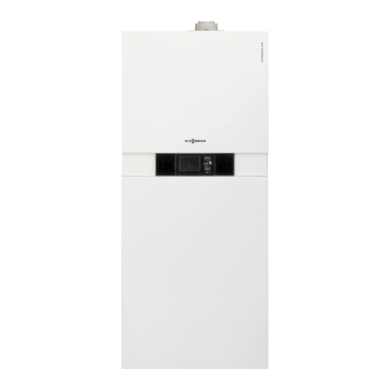
Vitodens 222-F, B2TB
Models 19, 35, 68, 125
Floor mounted, gas-fired condensing storage combi boiler
For operation with natural gas and liquid propane gas
Heating input: 12 to 125 MBH
3.5 to 37 kW
VITODENS
5461 889 - 16
01/2019
222-F
r
H
Product may not be exactly as shown
IMPORTANT
Read and save these instructions
for future reference.
Please file in Service Binder
Advertisement
Table of Contents

Subscribe to Our Youtube Channel
Related Manuals for Viessmann B2TB004


Summary of Contents for Viessmann B2TB004
- Page 1 Installation Instructions for use by heating contractor Vitodens 222-F, B2TB Models 19, 35, 68, 125 Floor mounted, gas-fired condensing storage combi boiler For operation with natural gas and liquid propane gas Heating input: 12 to 125 MBH 3.5 to 37 kW VITODENS 222-F Product may not be exactly as shown...
-
Page 2: Safety, Installation And Warranty Requirements
Follow the manufacturing facilities. Viessmann maintenance schedule of the boiler contained Contaminated combustion air will damage the boiler in this manual. and may lead to substantial property damage, severe Operating and Service Documentation personal injury and/or loss of life. -
Page 3: About These Installation Instructions
Safety Vitodens 222-F, B2TB 19, 35, 68, 125 Installation Safety, Installation and Warranty Requirements (continued) Suppliers of fiberglass wool products recommend the Fiberglass wool and ceramic fiber materials following precautions be taken when handling these materials: WARNING - Avoid breathing fiberglass dust and contact with skin and eyes. -
Page 4: Table Of Contents
Table of Contents Vitodens 222-F, B2TB 19, 35, 68, 125 Installation Page Safety Safety, Installation and Warranty Requirements....2 Product documentation..........2 Warranty..............2 Licensed professional heating contractor....2 Contaminated air............2 Advice to owner............2 Carbon monoxide.............2 Fresh air..............2 Equipment venting...........2 About these Installation Instructions......3 General Information Important Regulatory and Installation Requirements..6 Codes...............6... - Page 5 Table of Contents Vitodens 222-F, B2TB 19, 35, 68, 125 Installation Page Boiler Connections Safety Connections...........29 (continued) Low water cut-off..........29 Waterside Flow............30 Waterside flow (primary circuit).......30 Installation Examples..........31 System Layout 1-8...........32 Alternative Connection..........40 Control Connections Wiring Diagram............41 Electrical Connections..........43 Power supply connection of accessories....43 Connection of accessories........43 Accessories Connection..........44 Connection of accessories........44...
-
Page 6: Important Regulatory And Installation Requirements
- Service Instructions - Operating Instructions and User’s Information Manual Working on the equipment - Instructions of other Viessmann products utilized and The installation, adjustment, service, and maintenance installed of this boiler must be done by a licensed professional... -
Page 7: Flow Switch Procedure
CSD-1 Field Testing of High Limit Switches for Vitodens boilers – where required by law. VIESSMANN IS NOT RESPONSIBLE FOR ANY DAMAGES THAT THE FOLLOWING TEST PROCEDURE MAY RESULT IN BY OVERHEATING THE SYSTEM. -
Page 8: Applicability
General Information Vitodens 222-F, B2TB 19, 35, 68, 125 Installation Applicability CAUTION The boiler serial number must be provided when ordering replacement parts. IMPORTANT When ordering replacement parts, provide either the 16-digit boiler serial number (on the bar code label) or the 12-digit ASME/NB serial number, located as shown underneath boiler front enclosure panel. -
Page 9: Mechanical Room
General Information Vitodens 222-F, B2TB 19, 35, 68, 125 Installation Mechanical Room During the early stages of designing a new home, we recommend that proper consideration be given to constructing a separate mechanical room dedicated to the gas- or oil-fired heating equipment and domestic hot water storage tank(s). The boiler must be located in a heated indoor area, near a floor drain, and as close as possible to a wall. -
Page 10: Before Set-Up
(spraying, splashing, etc.) during boiler operation and service. Minimum Clearances Recommended minimum service clearances For typical Vitodens installations, Viessmann recommends installing the boiler with the service clearances shown in the illustration on the left. Note: The 12 in. (305 mm) side clearance specified is... -
Page 11: Connections
Boiler Connections Vitodens 222-F, B2TB 19, 35, 68, 125 Installation Connections Boiler water connection and piping Use an approved pipe sealant or teflon tape when connecting the following installation fittings. This section constitutes an overview only! Refer to subsequent sections for detailed information on individual piping connections. - Page 12 Boiler Connections Vitodens 222-F, B2TB 19, 35, 68, 125 Installation Connections (continued) Legend Condensate Drain (side) Note: The dimensional drawing shows example fittings for upward connection and connection to the left/right. Order the connection sets separately as accessories. For the dimensions of the individual connection sets, see the design information.
-
Page 13: Boiler Venting
Boiler Connections Vitodens 222-F, B2TB 19, 35, 68, 125 Installation Connections (continued) Boiler venting The Vitodens 222-F B2TB boiler comes with a pre-installed vent pipe adaptor C. Run venting system, single-wall or coaxial, through the side wall or the roof, taking the shortest possible route and at a rising angle (min. -
Page 14: Gas Shut-Off Valve Connection
Boiler Connections Vitodens 222-F, B2TB 19, 35, 68, 125 Installation Connections (continued) 2. Before connecting boiler to gas line, install ground joint union, capped drip leg and a manual equipment shutoff valve as shown. Valves must be listed by a nationally recognized testing agency. -
Page 15: Gas Piping Pressure Test
Boiler Connections Vitodens 222-F, B2TB 19, 35, 68, 125 Installation Connections (continued) Gas piping pressure test Flue gas connection When performing the gas piping pressure test, ensure the Connect the balanced flue. following requirements are met. See Venting Installation Instructions. WARNING Never check for gas leaks with an open flame. -
Page 16: Removing The Front Panels
Boiler Connections Vitodens 222-F, B2TB 19, 35, 68, 125 Installation Connections (continued) Removing the front panels 1. Remove the front upper panel. 2. Tilt the lower front panel. 3. Remove the retaining screw and set aside. 4. Lift up and out to remove the lower front panel. 5. -
Page 17: Accessing The Control Unit Connections
Boiler Connections Vitodens 222-F, B2TB 19, 35, 68, 125 Installation Connections (continued) Accessing the control unit connections 1. Remove both screws from the external accessory connection box front plate and set aside. 2. Remove both retaining screws as shown and set aside. - Page 18 Boiler Connections Vitodens 222-F, B2TB 19, 35, 68, 125 Installation Connections (continued) 5. Tilt the bottom of the external accessory connection box cover forward. 6. Pull the cover up to clear the locating pins and out to remove, then set aside. 7.
- Page 19 Boiler Connections Vitodens 222-F, B2TB 19, 35, 68, 125 Installation Connections (continued) 10. Release locking tabs as shown. 11. Remove cover. 12. Route all connecting cables to the appropriate areas and secure the cables to the control base using existing strain reliefs as shown. CAUTION When running and securing connecting cables on site, ensure that the maximum permissible temperatures of...
-
Page 20: External Accessory Connection Box
Boiler Connections Vitodens 222-F, B2TB 19, 35, 68, 125 Installation Connections (continued) External accessory connection box Note: See wiring diagram on page 41 for connection to the control base. IMPORTANT Electrical installations must comply with the latest edition of: In the U.S.A., the National Electrical Code (NEC), ANSI/NFPA 70 and any other state, local codes and/or regulations. -
Page 21: Boiler Control Base
Boiler Connections Vitodens 222-F, B2TB 19, 35, 68, 125 Installation Connections (continued) Boiler control base Note: See wiring diagram on page 20 for connection to the external accessory connection box. OUTDOOR TEMPERATURE SENSOR... -
Page 22: Condensate Connection
Boiler Connections Vitodens 222-F, B2TB 19, 35, 68, 125 Installation Preparing for Installation Condensate connection The Vitodens 222-F B2TB boiler comes with a built-in condensate trap. An external trap is not required when connecting the field drain to flexible discharge tubing. Discharge tubing (field supplied) must be of 1 in. -
Page 23: Vertical Piping Installation
Boiler Connections Vitodens 222-F, B2TB 19, 35, 68, 125 Installation Vertical Piping Installation 1. Install the restraining rings to the restraining bar (note their position). 2. Rotate the restraining rings a turn to lock into place (the ring opening should be facing to the side). 3. - Page 24 Boiler Connections Vitodens 222-F, B2TB 19, 35, 68, 125 Installation Vertical Piping Installation (continued) 1. Install the O-rings over the male connection boiler fittings. Ensure that the O-rings are properly seated in the groove. 2. Slide the insulation sleeve over the DHW pipe (as shown).
- Page 25 Boiler Connections Vitodens 222-F, B2TB 19, 35, 68, 125 Installation Vertical Piping Installation (continued) 1. Install the supplied locking clips over the bottom boiler connection and pipes. 2. Remove the cap from the factory installed gas line. 3. Install the supplied tees, drain valves and gas valve as shown.
-
Page 26: Side Piping Installation
Boiler Connections Vitodens 222-F, B2TB 19, 35, 68, 125 Installation Side Piping Installation 1. Install the restraining rings to the restraining bar (note their position). 2. Rotate the restraining rings a turn to lock into place (the ring opening should be facing down). 3. - Page 27 Boiler Connections Vitodens 222-F, B2TB 19, 35, 68, 125 Installation Side Piping Installation (continued) 1. Remove the tie-wrap holding the factory installed gas line. 2. Gently form the fexible gas line by bending the gas line at the middle to the desired side . IMPORTANT Ensure not to kink the gas line during bending.
-
Page 28: Installing Boiler Safety Devices
Boiler Connections Vitodens 222-F, B2TB 19, 35, 68, 125 Installation Side Piping Installation (continued) 1. Remove the cap from the factory installed gas line. 2. Install the supplied tees, drain valves and gas valve as shown. Installing boiler safety devices 1. -
Page 29: Safety Connections
Boiler Connections Vitodens 222-F, B2TB 19, 35, 68, 125 Installation Safety Connections Low water cut-off A low water cut-off may be required by local codes. Do not install an isolation valve between boiler and low water cut-off. WARNING Exposing the boiler to pressures and temperatures in excess of those listed will result in damages, and will render warranty null and void. -
Page 30: Waterside Flow
If system flow rate exceeds boiler maximum flow rate (as stated above), falls below the minimum flow rate or if system flow rate is unknown, Viessmann strongly recommends the installation of a low-loss header. Once the low-loss header is connected, the built-in low-... -
Page 31: Installation Examples
IMPORTANT The examples on the following pages depict possible piping layouts of the Vitodens 222-F boiler equipped with Viessmann System Technology. Please note that the following examples are simplified conceptual drawings only! Piping and necessary componentry must be field verified. -
Page 32: System Layout 1-8
Installation Examples Vitodens 222-F, B2TB 19, 35, 68, 125 Installation System Layout 1 Vitodens 222-F, B2TB with a direct-connected heating circuit with integrated DHW production Installation of ... Legend radiator heating circuit (high-temp. circuit) ■ A Vitodens 222-F B2TB boiler with DHW production ■... - Page 33 30, Low-loss header or if the system flow rates are unknown. Pressure relief valve outlet The low-loss header is available as accessory part. Viessmann temperature sensor for low-loss header ? Heating circuit pump 28/20 DCW inlet...
- Page 34 Installation Examples Vitodens 222-F, B2TB 19, 35, 68, 125 Installation System Layout 3 Vitodens 222-F, B2TB with... - Integrated DHW production - one heating circuit with mixing valve and system separation Legend Installation of ... Vitodens 222-F B2TB boiler with underfloor heating circuit with 3-way mixing valve ■...
- Page 35 Installation Examples Vitodens 222-F, B2TB 19, 35, 68, 125 Installation System Layout 4 Vitodens 222-F, B2TB with... - Integrated DHW production - one direct-connected heating circuit - one heating circuit with a mixing valve Installation of different heating circuits... Legend Vitodens 222-F B2TB boiler with radiator heating circuit (high-temp.
- Page 36 Heating pump temperature level of the under floor heating circuit, is 28/20 controlled by an accessory kit for a heating circuit with Low-loss header Viessmann temperature sensor for low-loss header ? mixing valve. DCW inlet DHW outlet DHW circulating pump sA...
- Page 37 Installation Examples Vitodens 222-F, B2TB 19, 35, 68, 125 Installation System Layout 6 Vitodens 222-F, B2TB with... - Integrated DHW production - one direct-connected heating circuit - one heating circuit with system separation Legend Installation of different heating circuits... Vitodens 222-F B2TB boiler with Vitotronic 200, HO1B outdoor reset control two heating circuits with 3-way mixing valve ■...
- Page 38 Installation Examples Vitodens 222-F, B2TB 19, 35, 68, 125 Installation System Layout 7 Vitodens 222-F, B2TB with... - one direct-connected heating circuit - three heating circuits with mixing valve and integrated DHW production Legend Vitodens 222-F B2TB boiler with Vitotronic 200, Installation of different heating circuits...
- Page 39 Installation Examples Vitodens 222-F, B2TB 19, 35, 68, 125 Installation System Layout 8 Vitodens 222-F, B2TB with... - Integrated DHW production - three zone circuits Legend Installation of different heating circuits... Vitodens 222-F boilers DHW production ■ Low-loss header 3 zone circuits ■...
-
Page 40: Alternative Connection
Installation Examples Vitodens 222-F, B2TB 19, 35, 68, 125 Installation Alternative Connection The following piping diagram reflects the connection for the DHW system to boiler. Legend Boiler Outdoor temperature sensor ! Vitotrol remote (optional) DHW storage tank Boiler pump DHW circulating pump sA Expansion tank Diverting valve Boiler heat exchanger... -
Page 41: Control Connections
Control Connections Vitodens 222-F, B2TB 19, 35, 68, 125 Installation Wiring Diagram WARNING CAUTION DISCONNECT POWER BEFORE Label all wires prior to disconnection SERVICING BOILER. when servicing controls. Wiring errors can cause improper and dangerous If any of the original wires as operation. - Page 42 Control Connections Vitodens 222-F, B2TB 19, 35, 68, 125 Installation Wiring Diagram (continued) Legend IMPORTANT Outdoor Temperature Sensor Supply Temperature Sensor/Low Loss Header Electrical installations must comply with the latest edition of: Boiler Temperature Sensor DHW Supply Temperature Sensor In the U.S.A., the National Electrical Code (NEC), DHW Tank Temperature Sensor ANSI/NFPA 70 and any other state, local codes and/or Ionization Electrode...
-
Page 43: Electrical Connections
Control Connections Vitodens 222-F, B2TB 19, 35, 68, 125 Installation Electrical Connections Power supply connection of accessories Cabling required for: The power supply connection of accessories can be made H outdoor temperature sensor directly at the control. The connection is activated and H Vitotronic 200-H, HK1B mixing valve control deactivated with the system on/off switch. -
Page 44: Accessories Connection
Control Connections Vitodens 222-F, B2TB 19, 35, 68, 125 Installation Accessories Connection Connection of accessories If the current flowing to the connected working parts (e.g. circulation pumps) is higher than the safety level of Install a disconnect switch in the power supply line the accessory, the output concerned should only be used that simultaneously isolates all live conductors from to control an on-site relay. -
Page 45: Accessing The X3 Plug
Control Connections Vitodens 222-F, B2TB 19, 35, 68, 125 Installation Accessing the X3 Plug 1. Remove the control unit cover (see page 19). 2. Remove the X3 plug from the control board. Attach sensors and reinsert the X3 plug. Refer to the following sensor information. -
Page 46: Connecting The Outdoor Temperature Sensor
Control Connections Vitodens 222-F, B2TB 19, 35, 68, 125 Installation Connecting the Outdoor Temperature Sensor 1. Remove cover of outdoor temperature sensor. 2. Mount wall-mount base (cable entry must point downward). IMPORTANT The outdoor temperature sensor should be mounted 6.6 to 8.2 ft. -
Page 47: Lon Module
Control Connections Vitodens 222-F, B2TB 19, 35, 68, 125 Installation LON Module Installing the LON module to the boiler control board 1. Remove the control cover (see page 19). 2. Insert the LON module into the boiler control board. 3. Connect the LON connector cable to the LON module. Connecting the LON module cable See the Vitotronic 200-H HK1B Installation Instructions. -
Page 48: Routing The Connecting Cables
Control Connections Vitodens 222-F, B2TB 19, 35, 68, 125 Installation Routing the Connecting Cables Note: If connecting cables touch hot components they will be damaged. When routing and securing connecting cables on site, ensure that the maximum permissible temperatures for these cables are not exceeded. Remove the existing cable grommet when using larger cross-sections [up to 9/16 in. -
Page 49: External 0-10 Volt Signal Connection
Control Connections Vitodens 222-F, B2TB 19, 35, 68, 125 Installation External 0-10 Volt DC Signal Connection 1. Connect the external 0-10VDC signal to plug 0-10VDC located in the external connection accessory box. 2. Ensure correct polarity. 3. See chart for maximum possible boiler water temperature and required signal. -
Page 50: Connecting A 24 Vac Thermostat
Control Connections Vitodens 222-F, B2TB 19, 35, 68, 125 Installation Connecting a 24 VAC Thermostat 1. Connect normally open dry contact of the switching relay (‘T-T’ contact) to terminal DE1, DE2 or DE3 of the EA1 module located in the boiler electrical junction box. -
Page 51: Zone Circuit Thermostat Connections
Control Connections Vitodens 222-F, B2TB 19, 35, 68, 125 Installation Zone Circuit Thermostat Connections Legend A Room thermostat (dry contact) zone circuit 1 B Room thermostat (dry contact) zone circuit 2 C Room thermostat (dry contact) zone circuit 3 D EA1 module (integrated into the boiler) -
Page 52: Zone Circuit Pump Connection
Control Connections Vitodens 222-F, B2TB 19, 35, 68, 125 Installation Zone Circuit Pump Connection Connection to boiler Pump output assignment is done using the set-up wizard. A maximum of 2 zone circuit pumps can be connected to the boiler additional pumps will require the use of an AM1 extension module. -
Page 53: Accessory Kit
Control Connections Vitodens 222-F, B2TB 19, 35, 68, 125 Installation Accessory Kit Boiler The mixing valve controller kit can only be used with wall-mounted gas-fired hot water heating boilers and Control a weather-responsive control; it can be used as an alternative for a Vitotronic control. -
Page 54: Closing The External Accessory Connection Box
Control Connections Vitodens 222-F, B2TB 19, 35, 68, 125 Installation Closing the External Accessory Connection Box 4. Tilt the top of the external accessory connection box cover forward. 5. Drop down over the locating pins and set the cover in place. 6. -
Page 55: Reinstalling The Front Enclosure Panel
Install lower front panel. Install upper front panel. IMPORTANT Read and follow, where applicable, the safety instructions of all labels and stickers attached to boiler surfaces. Do not remove any of these instructions. Contact Viessmann if any replacement labels are required. -
Page 56: Technical Data
Additional Information Vitodens 222-F, B2TB 19, 35, 68, 125 Installation Technical Data Boiler Model No. 222-F B2TB 19, 68 35, 125 CSA input Natural Gas (NG) 12-68 19-125 (kW) (3.5-20) (5.5-37) 12-68 CSA input Liquid Propane Gas (LPG) 31-125 (kW) (3.5-20) (9-37) CSA output/DOE *1... - Page 57 *11 Measured values are based on room temperature of 68ºF (20ºC) and a domestic hot water temperature of 149ºF (65ºC). *12 Add 1f in. (40 mm) when using the optional accessory seismic bracket kit. For information regarding other Viessmann System Technology componentry, please reference documentation of respective product.
-
Page 58: Installation Fittings
Additional Information Vitodens 222-F, B2TB 19, 35, 68, 125 Installation Installation Fittings Parts for Top Connection 0302 Connecting pipe, DHW/heating 0303 Support bracket with pipe clips 0304 Pipe clip (each) 0307 Connector retaining clip (Set of 2) *1 0308 Pipe insulation, 19x9x740 mm 0310 Gas ball valve, ¾... -
Page 59: Lighting And Operating Instructions
Additional Information Vitodens 222-F, B2TB 19, 35, 68, 125 Installation Lighting and Operating Instructions FOR YOUR SAFETY READ BEFORE OPERATING W A R N I N G: If you do not follow these instructions exactly, a fire or explosion may result causing property damage, personal injury or loss of life. A. - Page 60 Vitodens 222-F, B2TB 19, 35, 68, 125 Installation...
Need help?
Do you have a question about the B2TB004 and is the answer not in the manual?
Questions and answers