
Related Manuals for Johnson Controls T9180


Summary of Contents for Johnson Controls T9180
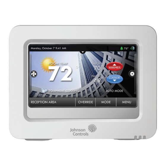
- Page 1 T9180 Commercial Digital Thermostat High Resolution Touch Screen Owner’s Manual and Installation Instructions Code No. LIT-12012449 Issued October 3, 2017...
- Page 2 5.10. Firmware releases after rev. 5.10 may not be adequately depicted in this manual. Please refer to the appropriate website or contact your place of purchase to learn about changes to the thermostat after firmware release 5.10. T9180...
- Page 3 Glossary of Terms Auto-Changeover: A mode in which the thermostat will turn on the heating or cooling based on room temperature demand. Cool Setpoint: The warmest temperature that the space should rise to before cooling is turned on (without regard to deadband). Deadband: The number of degrees the thermostat will wait, once a setpoint has been reached, before energizing heating or cooling.
-
Page 4: Table Of Contents
Table of Contents GET TO KNOW YOUR THERMOSTAT Home Screen ..................1 Menu Screens ..................1 Dropdown Dashboard .................2 Care and Use of Your Thermostat .............5 QUICK START Selecting Your Desired Temperature and Mode ......6 Using the Fan Button .................6 Using the Override Button ..............7 Setting the Time &... - Page 5 Table of Contents ALERTS .....................21 View Current Alerts ..............22 Reset Alerts ................22 Set/Edit Reminders ..............22 Service Information (Who To Call For Service) ....22 DISPLAY ..................23 Active Brightness ..............24 Idle Brightness ................ 24 Night Dimmer ................. 24 Maintenance ................
- Page 6 Table of Contents GENERAL SETUP ................40 Units (F or C) ................40 Language ..................41 Smart Recovery On/Off .............41 AUTOMATED DEMAND RESPONSE ..........42 INSTALLATION SETTINGS...............56 Heat & Cool Stages ..............56 Heat & Cool Stages ...............56 Compressor Stages ..............56 Aux Heat Stages ..............56 Timers &...
- Page 7 Determining Your Existing Wiring and Equipment ......74 Making 4 Wires Work When 5 Wires Are Required ....76 Making 5 Wires Work When 6 Wires Are Required ....77 The T9180 Thermostat Backplate ..........78 Explanation Of the Thermostat Dip Switches ......79 Sample Wiring Diagrams..............80 TROUBLESHOOTING ..............83...
-
Page 8: Get To Know Your Thermostat
Get To Know Your Thermostat Home Screen Outdoor Temperature Backlit Color Touch Display (If optional accessory is used Drop Down or connected to Skyport) Sensor Button Connectivity Symbol Connectivity Symbol Table Warmer Not connected Button to Wi-Fi SD Card Connected to local Slot access point w/IP address without... -
Page 9: Dropdown Dashboard
Get To Know Your Thermostat Dropdown Dashboard The Dropdown Dashboard displays temperature, and other readings. It will also show the high and low readings of the day. Wi-Fi Drop Down Connection Dashboard Button Icon Connectivity Symbol Table Not connected to Wi-Fi Connected to local access point w/IP address without... - Page 10 Get To Know Your Thermostat Dropdown Dashboard (The contents of your Dashboard may vary) Weather Display with forecast for the following 3 days (Skyport connection required for weather) Weather Display This page displays sensor information. Select ‘Onboard’ to view room temperature sensors that are built-into the thermostat.
- Page 11 Get To Know Your Thermostat These 3 screens are for informational purposes only. Settings may not be changed from these screens. Thermostat Info Equipment Configuration Thermostat Outputs...
-
Page 12: Care And Use Of Your Thermostat
Get To Know Your Thermostat Care and Use of Your Thermostat Pencils, pens and other sharp objects should never be used on your thermostat; these may damage your touch screen. Only use your finger tip to press the screen buttons. Use a soft, damp cloth to clean the screen. -
Page 13: Quick Start
Quick Start - Temperature, Modes and Fan Selecting Your Desired Temperature and Mode Cool Setpoint Press Warmer Button to adjust temperature The Heat or Cool Setpoint is the temperature the room Cooler has to reach before heating Button or cooling will turn off. Heat Setpoint Press or the MODE Icon... -
Page 14: Using The Override Button
Quick Start - Override Using the Override Button OVERRIDE NOTE: Override may only be used when the thermostat is set to Program RUN or Holiday ON modes. Override Unoccupied Operation - During programmed, unoccupied periods, pressing the OVERRIDE button will force the thermostat into Occupied 1 settings. When the OVERRIDE button is pressed, a timer screen will appear and allow the user to choose from 30 minutes to up to 4 hours of override time. -
Page 15: Setting The Time & Date
Quick Start - Set Time & Date NOTE: When the thermostat is connected to a Skyport account, the Time & Date are automatically synchronized to the Skyport Cloud, including automatic Daylight Savings adjustments. Set Time & Date Your time zone is selected in the Skyport web application. Set Current Time Use AM/PM - ON Set Current Date... -
Page 16: Setting The Time
Quick Start - Set Time & Date Setting the Time Press then to scroll down. MENU Press Set Time & Date Press Set Current Time (12:00 AM) min + hr + Press to set the current time. hr - min - Press when finished. -
Page 17: Setting The Date
Quick Start - Set Time & Date Setting the Date Press Set Current Date 6/1/2013 Press to set the current month and year. Press the day on the calendar Press BACK when finished. Daylight Savings Setup Turn Daylight Savings Daylight Savings Time - OFF Time on or off. -
Page 18: Connecting To Wi-Fi
Quick Start - Connect to Wi-Fi Connect to Wi-Fi (from initial start up) When power is connected to the thermostat and it has not been configured to connect to a Wi-Fi Access point, the following message appears: Wi-Fi Set Up No Wi-Fi access points are configured for your thermostat. -
Page 19: Wifi Set Up - Create A Skyport Account
Quick Start - Connect to Wi-Fi (from menus) MENU Press MENU Press DOWN Press Wi-Fi • Wi Fi Setup Press Wi-Fi Setup Select the access point from the list that you want to connect to. Enter the password for the Wi-Fi Access Point and press NEXT. Select automatic setup and press NEXT. - Page 20 Quick Start - Connect to Wi-Fi (from menus) Although there is more than one way to create a Skyport account, the steps below illustrate creation from a browser. If the thermostat is connected to the local Wi-Fi Access Point, but not yet joined to a Skyport account, you may join the thermostat to an account by doing the following: Select MENU from the thermostat’s home screen.
-
Page 21: Schedule
Main Menu Buttons - Schedule Schedule View My Schedule Edit My Schedule Unoccupied Settings Mode (Auto) Auto Heat Cool Heat Setpoint (55˚) Cool Setpoint (85˚) -
Page 22: View My Schedule
Main Menu Buttons - Schedule This thermostat features up to 3 Occupied time periods per 24 hour day. Schedule View My Schedule Press a day of the week to view its settings. This may be repeated for each day. Edit My Schedule Press and select day(s) to program Select individual day(s) Select groups of day(s) - Page 23 Main Menu Buttons - Schedule Edit My Schedule (Continued) Adjust Mode, Start Time, Stop Time, and Heat and Cool Setpoints to desired settings. The Time Period May also be Enabled or Disabled. Un-check the enabled box for Time Periods you don’t want to use. Press DONE when finished.
-
Page 24: Fan Settings
Main Menu Buttons - Fan Settings Fan Settings Fan - Auto Who To Call For Service Occupied Fan State (Auto) Auto Fan Purge - OFF View Runtime Graphs Preoccupancy Purge Time (15 mins) -
Page 25: Fan On/Off Auto
Main Menu Buttons - Fan Settings The fan may be set to run continuously during Heat, Cool, Auto, and Occupied modes. A Preoccupancy Fan Purge Fan Settings schedule may also be set. Press to turn fan On to run continuously or Auto for fan to run only with heating or cooling. -
Page 26: Screensaver
Main Menu Buttons - Screensaver Screensaver Screensaver - OFF Who To Call For Service Screensaver Setup View Runtime Graphs Screensaver Turn On Delay Screensaver Type Slideshow Digital Clock Analog Clock Change Image After... Use Theme Images - Off Randomize Slideshow - Off Show Clock - OFF Home Screen Info - OFF Screensaver Preview... -
Page 27: Screensaversetup
Main Menu Buttons - Screensaver The Screensaver allows you to create custom slideshows. Screensaver Screensaver - OFF Screensaver - ON Screensaver Setup Screensaver Turn On Delay (5m) How long after a button press for the Screensaver to appear. 1, 3, 5, or 30 minutes Screensaver Type (Slideshow) Slideshow, Digital Clock, Analog Clock... -
Page 28: Alerts
Main Menu Buttons - Alerts Alerts View Current Alerts Reset Alerts Reset Air Filter Alert Reset UV Lamp Alert Set/Edit Reminders Service Call Reminder - OFF Days Until Service Call (0 days) Air Filter Reminder - OFF Set Max Filter Runtime (300 hrs) Set Max Filter Days (0 days) -
Page 29: View Current Alerts
Main Menu Buttons - Alerts The alerts let you know when your system needs service. Alerts View Current Alerts View and reset current Alerts will appear service alerts here. on the bottom bar of the Home Screen. Press to view and reset current alerts. -
Page 30: Display
Main Menu Buttons - Display Display Active Brightness Idle Brightness Night Dimmer Auto Night Dimmer - OFF Set Idle Brightness Set Dimmer Schedule Maintenance Screen Cleaning Touch Calibration... -
Page 31: Active Brightness
Main Menu Buttons - Display The display brightness options may be adjusted in this menu. Display Active Brightness (80%) You may select how bright the backlight is while the thermostat is active. The display is active for 3 minutes after last touch, it then goes Idle. Idle Brightness (30%) You may select how bright the backlight is while the thermostat is idle. -
Page 32: Maintenance
Main Menu Buttons - Display Maintenance Maintenance allows you to clean and calibrate the touch screen. Screen Cleaning Screen Cleaning Mode disables the touch feature for 15 seconds so the screen may be cleaned without altering any settings. Use a soft cloth without solvents or abrasive cleaners. Touch Calibration Under normal circumstances, the touch screen should not need to be calibrated. -
Page 33: Preferences
Main Menu Buttons - Preferences Preferences User Interface Themes Custom Wallpaper Heat/Cool Indicator Heat/Cool Indicator OFF Taskbar red/white OFF Room Temp red/blue OFF Mode Status red/blue OFF Sound Options Beep - OFF Beep Sound... -
Page 34: User Interface Themes
Main Menu Buttons - Preferences You may set the type of background that appears on the thermostat Preferences Home Screen. User Interface Themes (ocean) This thermostat has several high quality background themes to choose from. NOTE: At 7pm, the background will change to an evening scene. At 7am it will return to a daytime scene. -
Page 35: Holidays
Main Menu Buttons - Holidays Holidays Holiday Schedule - OFF Edit Holidays Preset Holidays... -
Page 36: Holiday Schedule On/Off
Main Menu Buttons - Holidays The Holiday Schedule allows the Color Touch Screen to follow a fully customizable preset, weekly, monthly, and yearly holiday program. The thermostat will Holidays stay in Unoccupied settings while Holiday is active. Holiday Schedule - OFF Press to turn Holiday Schedule On or Off. - Page 37 Main Menu Buttons - Holidays Edit Holidays (Continued) Deselecting Holidays You may deselect a holiday simply by pressing on it. Press BACK to save your changes and return to the Holiday menu. If you choose to deselect a holiday that is part of a Custom Repeating Program, the screen below will appear.
-
Page 38: Preset Holidays
Main Menu Buttons - Holidays Edit Holidays (Continued) Editing Repeating Holidays (continued) You may now delete all repeating custom holidays in this group by pressing the ON box to uncheck your selection. Press SAVE to return to Holiday editing screens. Preset Holidays You may choose from several standard preset holidays to observe. -
Page 39: Security
Main Menu Buttons - Security Security Auto Screenlock Auto Screenlock - OFF Set Passcode Lock After... Allow fan/mode changes - NO Allow setpoint changes - NO Allow override - NO Setpoint Limits Setpoint Limits - OFF Minimum Cool Setpoint Maximum Heat Setpoint Maximum Override Time... -
Page 40: Auto Screenlock
Main Menu Buttons - Security Security settings may be set to limit or prevent changes to your thermostat. Security Auto Screenlock Auto Screenlock - OFF NOTE: Code must be Auto Screenlock - ON set before Auto Screenlock can Set Passcode (code not set ) be turned on. -
Page 41: Information
Main Menu Buttons - Information Information View Runtime Graphs Last 7 Days - Cooling Last 7 Days - Heating Last 7 Days - Override Delete Runtime Data Who To Call For Service... -
Page 42: View Runtime Graphs
Main Menu Buttons - Information This button contains valuable service and system runtime information. Information View Runtime Graphs Track your system’s runtime/energy usage. Last 7 Days - Cooling Press the information icon to learn more about each graph. *NOTE: The runtime graphs are updated Last 7 Days - Heating at 12:00 AM each day. -
Page 43: Settings
Main Menu Buttons - Settings Settings Thermostat Name Available Modes All Modes Including Auto Heat and Cool Heat Only Cool Only SD Card Import Settings from SD Card Export Settings to SD Card General Setup Units Fahrenheit Celsius Language English Spanish/Espanol French/Francais Smart Recovery - ON/OFF... - Page 44 Main Menu Buttons - Settings Settings (Continued) Installation Settings Timers & Deadbands Cycles Per Hour Min Heat/Cool Difference Compressor Min Off Time 1st Stage Deadband 2nd Stage Deadband 2nd Stage Deadband 2nd Stage Timer 2nd Stage Turnoff Point Deadband Setpoint 3rd Stage Deadband 3rd Stage Deadband 3rd Stage Timer...
- Page 45 Main Menu Buttons - Settings Settings (Continued) Installation Settings Heat Pump Settings Heat Pump Lockout - Enabled/Disabled HP Lockout Outdoor Temp Aux Heat Lockout - Enabled/Disabled Aux Heat Lockout Temp Dual Fuel Settings Dual Fuel - On/Off Changeover With Outdoor - On/Off Adjust Balance Point AUX Output Settings AUX Output Usage...
- Page 46 Main Menu Buttons - Settings Settings Installation Settings (Continued) Test Outputs Dealer Information Dealer Name Contact Name Dealer Phone Dealer Email Dealer Website Upgrade Firmware Delete Custom Images Factory Defaults Restart Thermostat...
-
Page 47: Thermostat Name
Main Menu Buttons - Settings Thermostat heating and cooling options are found in this menu. Settings Thermostat Name Use keypad to name your thermostat. The name is displayed on the Home Screen. (Up to 14 characters) Name appears here Available Modes (all) Choose the desired modes the thermostat will use: Heat, Cool, Heat &... -
Page 48: Language
Main Menu Buttons - Settings General Setup (Continued) Language (en) English Spanish/Español French/Français Smart Recovery - OFF Smart Recovery - ON Smart Recovery turns on the heat before the Occupied start time to bring the room temperature to the Occupied setpoint at the start of the Occupied time period. -
Page 49: Automated Demand Response
Main Menu Buttons - Settings Overview Automated Demand Response ColorDisplay thermostats support the handling of specific signals from the utility provider. The utility generated signals carry pricing information and/or setback actions that alter the comfort settings of the thermostat in order to reduce energy usage on demand. - Page 50 Main Menu Buttons - Settings The Demand Response configuration page, shown below, is where the thermostat is configured to respond to the energy provider’s signals. It also sets operational parameters for the thermostat. The left column of the ADR configuration page allows or prevents access by the utility.
- Page 51 Main Menu Buttons - Settings The right column of the ADR configuration page is where the occupant adjusts the operational parameters for ADR. The utility may send up to 3 types of ADR signals to Skyport. These are: 1) Pricing for the cost of energy, 2) An Offset to the occupants’...
- Page 52 Main Menu Buttons - Settings Selecting the Overview tab of the ADR page will cause a summary of ADR events to be displayed. Office - Configuration...
- Page 53 Main Menu Buttons - Settings Automated Demand Response Utility and Program setup must be done at the Skyport Cloud Services account. From the thermostat Home Screen, press the ‘Menu’ button, then select ‘Settings” . From the above screen the ‘Automated Demand Response’ button is pressed.
- Page 54 Main Menu Buttons - Settings Selecting the ‘Price Dependent Action’ button allows the user to determine what action is taken when the price rises above the set threshold. In the above example; if the price threshold is exceeded, the thermostat will invoke the ‘Offset Setpoints’ configured for an ADR event until the event is over.
- Page 55 Main Menu Buttons - Settings The user may limit the maximum Cooling Setpoint.
- Page 56 Main Menu Buttons - Settings The user may limit the minimum Heating Setpoint.
- Page 57 Main Menu Buttons - Settings The user may adjust the ADR Cooling ‘static’ Setpoint.
- Page 58 Main Menu Buttons - Settings The user may adjust the ADR Heating ‘static’ Setpoint.
- Page 59 Main Menu Buttons - Settings The user may adjust the ADR Cool offset. During an ADR event the cooling setpoint will be adjusted by the amount of degrees configured in this step.
- Page 60 Main Menu Buttons - Settings The user may adjust the ADR Heat offset. During an ADR event the heating setpoint will be adjusted by the amount of degrees configured in this step.
- Page 61 Main Menu Buttons - Settings When an ADR event is pending, and hasn’t started yet, there will be a yellow leaf on the top bar. This will be accompanied by associated text as shown below. During an ADR event there will be a green leaf on the top bar. This will be accompanied by associated text as shown below.
- Page 62 Main Menu Buttons - Settings If a Warmer or Cooler button is pressed during an active ADR event, then the user is presented with this opt-out screen. If a pricing triggered ADR event is enabled, there will be a green leaf on the top bar along with the actual cost of energy.
-
Page 63: Installation Settings
Main Menu Buttons - Settings Installation Settings Heat & Cool Stages (1h1c) Heat & Cool Stages (1h1c) Up to 2 Stages Cooling and 4 stages Heating. Compressor Stages (1h1c) Only available when Up to 2 compressors. dip switch is set for Heat Pump operation. - Page 64 Main Menu Buttons - Settings Installation Settings (Continued) Timers & Deadbands (Continued) The Deadband is the number of degrees or minutes that the thermostat waits before it initiates the stages of heating or cooling. 1st Stage Deadband Specifies the minimum temperature difference between the room temperature and the desired setpoint before the first stage of heating or cooling is allowed to turn on.
-
Page 65: Heat Pump Settings
Main Menu Buttons - Settings (Continued) Installation Settings (Only available Heat Pump Settings when dip switch is set for Heat Pump operation.) Heat Pump Lockout - DISABLED Heat Pump Lockout - ENABLED Turns on Heat Pump Lockout. HP Lockout Outdoor Temp (65˚) Heat Pump will not run below this temp. -
Page 66: Aux Output Settings
Main Menu Buttons - Settings Installation Settings AUX Output Settings... -
Page 67: Fan Off Delay
Main Menu Buttons - Settings (Continued) Installation Settings Fan Off Delay (0s) Runs the fan for a short time after Cooling or electric strip heat turns off to increase system efficiency. (0 - 120 Secs.) Sensor Settings Control Sensor (thermostat ) When a remote sensor is connected to the thermostat, the user may choose which sensor source is used to measure room temperature. -
Page 68: Calibrate Sensors
Main Menu Buttons - Settings Calibrate Sensors (0˚) The thermostat and wired sensor may be calibrated -7 to +7 degrees F . • Thermostat • Wired Sensor Test Outputs The installer or service technician can use this feature to test the functions without any time delays of the thermostat. -
Page 69: Dealer Information
Main Menu Buttons - Settings Dealer Information A Dealer may enter their company contact information for the customer to use when they need service. This will appear when the “Who To Call For Service” button is pressed in the Information Menu. Use the keyboard to enter your information. -
Page 70: Wi-Fi
Main Menu Buttons - Wi-Fi Wi-Fi Enabled Wi-Fi Status Wi-Fi Setup Choose Network Password Entry Local API Option Local API - OFF API Protocol HTTP HTTPS... -
Page 71: Status
Main Menu Buttons - Wi-Fi Wi-Fi Wi-Fi Enabled This option allows the wifi radio to be turned off or on. Wi-Fi Status It is here that you will find helpful information regarding the connectivity myoffice status of your thermostat, including the thermostat’s ID. Wi-Fi Setup Choose your network from the list and enter... -
Page 72: Secure Api
Main Menu Buttons - Wi-Fi This is the default with the local API OFF . • Local API - OFF • API Protocol (http) To turn on the HTTP Local API select Local API • Local API - ON • API Protocol (http) Press BACK to return to previous screen. - Page 73 Main Menu Buttons - Wi-Fi Upon pressing BACK, the screen will look like this. • Local API - OFF • API Protocol API Protocol (https) (http) • Basic Auth User PRESS • Basic Auth Password API Protocol (http) • Basic Auth User Select Basic Auth User, and enter (64 remaining) the appropriate information...
- Page 74 Main Menu Buttons - Wi-Fi • Basic Auth Password Select Basic Auth Password and (64 remaining) enter the appropriate information on the screen below and press DONE to save. Shift 123!? SPACE BACK Basic Auth Password DONE The last step is to turn the Local API on as shown below. •...
-
Page 75: Skyport
Main Menu Buttons - Skyport Skyport Skyport Services - ON Weather Updates - ON Skyport Account Skyport Account Pressing this button will let you know if you are paired with a Skyport account. If not, then you may follow prompt and instructions to create an account and add the thermostat to the account. -
Page 76: Emergency Heat
Main Menu Buttons - Emergency Heat The Emergency Heat function is only available if your thermostat is set to control a Heat Pump. Emergency Heat To initiate the Emergency Heat feature, Press the Emergency Heat button. During Emergency Heat operation the thermostat will turn on the fan and auxiliary stages of heat when there is a demand for heat. -
Page 77: Colordisplay Desktop App
ColorDisplay Desktop App may be downloaded at no charge at: http://jcithermostats.com/colordisplay/desktop-app/ Every time the user runs the ColorDisplay Desktop App software, it automatically connects to the Johnson Controls ColorDisplay website ® in the background and updates the software and firmware (the operating system for touch screen) at no cost. -
Page 78: Uploading Photos
The ColorDisplay Desktop App Uploading Photos and Settings to your thermostat When you are finished adding and editing photos and settings, click on Save to SD. When prompted, remove the SD card from the SD card reader on your computer. Save to SD *NOTE: A 2GB SD card is recommended. -
Page 79: Installation Instructions
Installation Instructions Remove and Replace the Old Thermostat To install the thermostat properly, please follow these step by step instructions. If you are unsure about any of these steps, call a qualified technician for assistance. • Installation tools: Small flat blade screwdriver, wire cutters and wire strippers. -
Page 80: Wire Connections
Installation Instructions Wire Connections If the terminal designations on your old thermostat do not match those refer to the chart below or the wiring on the new thermostat, diagrams that follow. Wire from the Install on the old thermostat Function new thermostat terminal marked connector marked... -
Page 81: Determining Your Existing Wiring And Equipment
Installation Instructions Before you go any further, determine what your existing wiring and equipment situation is. If you have a Heating only system without Air Conditioning, the JCI thermostat will require 3 wires: R (24Vac), C (24Vac) and W (Heat). Most systems that only have Heating use very simple thermostats that require 2 wires: the R (24Vac) and W (Heat). - Page 82 Installation Instructions If you have a heat pump without aux heat, the JCI model will require 5 wires: R (24Vac), C (24Vac), W1/O/B (Reversing Value), Y (1 Stage Compressor), and G (Fan). If you are short 1 wire, there are at least 2 options available to connect the JCI thermostat: 1.
-
Page 83: Making 4 Wires Work When 5 Wires Are Required
Installation Instructions Making 4 Wires Work When 5 Wires Are Required If you would like to install the JCI thermostat using only 4 wires when 5 are required, follow the directions below. You will need a screwdriver along with a 3" long piece of thermostat wire to use as a jumper: 1. -
Page 84: Making 5 Wires Work When 6 Wires Are Required
Installation Instructions Making 5 Wires Work When 6 Wires Are Required If you have a system that requires 6 wires, and you would like to install the JCI thermostat using only 5 wires, follow the directions below. You will need a screwdriver along with a 3" long piece of thermostat wire to use as a jumper: 1. -
Page 85: The T9180 Thermostat Backplate
Installation Instructions 9180 The T Thermostat Backplate NOTE: The backplate does not fully cover a full size vertical junction box. The ACC-WALLPLT touch screen wallplate or a single-gang, horizontally mounted junction box would be needed for that type of SENSOR installation. -
Page 86: Explanation Of The Thermostat Dip Switches
Installation Instructions Explanation of Thermostat Dip Switches Dip switches are located on the back of the thermostat GAS/EL ELEC This dip switch configures the thermostat to control a GAS/EL GAS/EL conventional gas/electric system or a heat pump. If your system is anything other than a heat pump, leave this switch set for GAS/EL.* *For some commercial heat pumps, this switch may need to be set for GAS/EL. -
Page 87: Sample Wiring Diagrams
Installation Instructions Sample Wiring Diagrams with Dip Switch Positions Conventional Heating and Cooling Systems 3 Wire, Heat Only 2 Wire, Heat Only Residential & Commercial 1 Stage Heating Residential & Commercial 1 Stage Heating with no Fan. with no Fan. The thermostat will not work with 24VAC Power 2 wires. - Page 88 Installation Instructions Sample Wiring Diagrams with Dip Switch Positions Heat Pump Systems 5 Wire, 1 Stage Cooling, 1 Stage Heat 6 Wire, 1 Stage Cooling, 2 Stage Heat Residential & Commercial Heat Pump with Residential & Commercial Heat Pump with ‘O’...
- Page 89 Installation Instructions Sample Wiring Diagrams Outdoor Sensor: ACC-RSEN Temperature Sensor 10K ohm sensor at 77F/25C. Negative Temperature Coefficient. Use 18-22 gauge thermostat wire. 10K Thermistor SENSOR Outdoor Sensor ACC-RSEN Indoor Remote Sensor with Override Button: ACC-RSEN-OVR Temperature Sensor 10K ohm sensor at 77F/25C. NegativeTemperature Coefficient. (see page 60 for setup instructions) Use 18-22 gauge thermostat wire.
-
Page 90: Troubleshooting
Troubleshooting • SYMPTOM: The thermostat touchscreen buttons are not responsive. CAUSE: The touchscreen is out of calibration. REMEDY: Remove the thermostat from the backplate. Push the thermostat back onto the backplate, while keeping your finger pressed firmly against the center of the touchscreen, until the Calibration screen appears. -
Page 91: Index
Index Home, 1 Deadband Mode, 1, 6 1st stage, 57 Menu, 1 2nd stage, 57 Warmer, 1 3rd stage, 57 4th stage, 57 Dealer Information, 35, 62 Accessories, 60, 61, 78 Delay Active Brightness, 24 Fan-off, see Fan Alerts, 22 Time between stages, view current, 22 see Time Delay... - Page 92 Index Emergency Heat, 69 Energy Watch Cool, 35 Heat, 35 Aux heat, 35 Heat Idle Brightness, 24 1st stage Information, 35 deadband, see Installation Settings, 41 Deadband Installation, 72 emergency heat, 69 minutes of runtime, 35 Factory Defaults 2nd stage deadband, resetting, 62 see Deadband Fahrenheit, 40...
- Page 93 Index Outdoor calibrate, 61 high and low temp, 1 sensor, 60 viewing temp, 1 Main Menu, 1 Schedule turn on/off, 15 Maintenance, 25 view, 15 Manual edit, 15 changeover, 6 Screen Cleaning, 25 cool, 6 Screensaver heat, 6 turn on/off, 20 Mode, 1, 6 Passcode, 30 setup, 20...
- Page 94 Index Terminals, W1, 73 78 see Backplate W2, 73, 78 Test Outputs, 61 W3, 73, 78 Thermostat Sensor Wallpaper, 27 calibrate, 61 Warranty, 88 Three Stage Heat, 56 Wiring, 73 Themes, 27 gas/electric, 80 Time, see Clock heat pump, 81 Timers, 56 Y1, 73, 78 Time Delay,...
-
Page 95: Warranty
Warranty Three-Year Warranty - This Product is warranted to be free from defects in material and workmanship. If it appears within three years from the date of original installation, whether or not actual use begins on that date, that the product does not meet this warranty, a new or remanufactured part, at the manufacturer’s sole option to replace any defective part, will be provided without charge for the part itself provided the defective part is returned to the distributor through a qualified servicing dealer. -
Page 96: Technical Specifications
Technical Specifications ColorDisplay Series Thermostat Controllers Touch Screen Series Thermostat Controllers Power Requirements 20 - 30 VAC 50/60 Hz, 4.8 VA @ 24V nominal. Output Rating W1, W2, W3 = 0.2A max, 0.01A min, 3A inrush, 20 - 30 VAC Y1, Y2, G = 0.4A max, 0.01A min, 3A inrush, 20 - 30 VAC Local Temperature Thermistor, NTC 10K @ 25C... - Page 97 Printed on recycled paper. LIT-12012449 Rev. 1 10/17...
Need help?
Do you have a question about the T9180 and is the answer not in the manual?
Questions and answers