Table of Contents
Advertisement
Quick Links
WARNING: If the information in this manual is not
followed exactly, a fire or explosion may result
causing property damage, personal injury or loss
of life.
Do not store or use gasoline or other flammable
vapors and liquids in the vicinity of this or any
other appliance.
WHAT TO DO IF YOU SMELL GAS
•
Open windows.
•
Do not touch electrical switches.
•
Do not try to light any appliance.
•
Extinguish any open flame.
•
Do not use the phone in your building.
•
Immediately call your gas supplier from a neigh-
bor's phone. Follow the gas supplier's instructions.
•
If you cannot reach your gas supplier, call the fire
department.
•
Installation and service must be performed by a
qualified installer, service agency or the gas sup-
plier.
WARNING
Do NOT use this appliance if any part has been under water.
Immediately call a qualified service technician to inspect the
appliance and to replace any part of the control system and
any gas control, which has been under water.
INSTALLER: Leave this manual with the appliance.
CONSUMER: Retain this manual for future reference.
INSTALLATEUR : Laissez cette notice avec l'appareil.
CONSOMMATEUR : Conservez cette notice pour consulta-
tion ultérieure.
85-03-00955
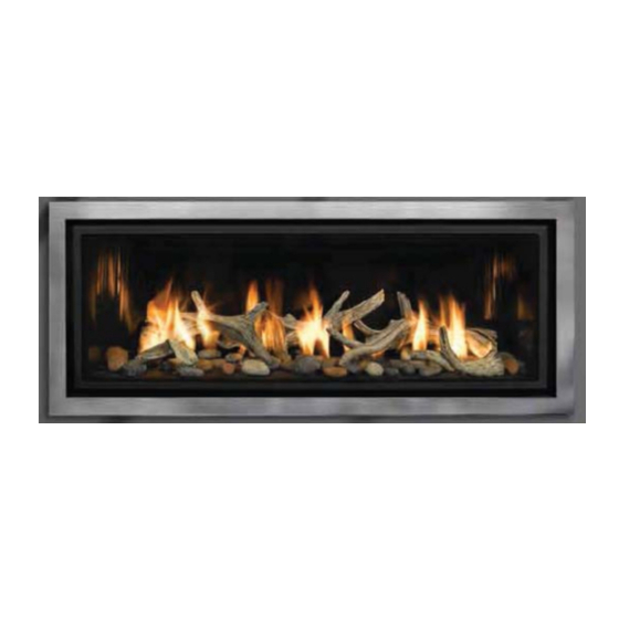
FULLVIEW LINEAR DIRECT VENT GAS FIREPLACE HEATER
Flush-Faced Model ML39-PF2, AA-11-02591
INSTALLATION and OPERATING INSTRUCTIONS MANUAL
DOCUMENT NO. ML39-PF2-0516
AVERTISSEMENT : Assurez-vous de bien suivre les in-
structions donné dans cette notice pour réduire au minimum
le risque d'incendie ou pour éviter tout dommage matéeriel,
toute blessure ou la mort.
•
Ne pas entreposer ni utiliser d'essence ni d'autres vape-
rurs ou liquides inflammables dans le voisinage de cet
appareil ou de tout autre appareil.
•
QUE FAIRE SI VOUS SENTEZ UNE ODEUR
GAZ:
•
Ne pas tenter d'allumer d'appareil.
•
Ne touchez à aucun interrupteur. Ne pas vous servir
des téléphones se trouvant dans le batiment où vous
vous trouvez.
•
Appelez immédiatement votre fournisseur de gaz depuis
un voisin. Suivez les instructions du fournisseur.
•
Si vous ne pouvez rejoindre le fournisseur de gaz, appe-
lez le service dos incendies.
•
L'installation et service doit être exécuté par un
installer, agence de service ou le fournisseur de gaz.
P a g e
| 1
DE
qualifié
Advertisement
Table of Contents

Subscribe to Our Youtube Channel
Related Manuals for Mendota FULLVIEW AA-11-02591


Summary of Contents for Mendota FULLVIEW AA-11-02591
- Page 1 FULLVIEW LINEAR DIRECT VENT GAS FIREPLACE HEATER Flush-Faced Model ML39-PF2, AA-11-02591 INSTALLATION and OPERATING INSTRUCTIONS MANUAL DOCUMENT NO. ML39-PF2-0516 WARNING: If the information in this manual is not AVERTISSEMENT : Assurez-vous de bien suivre les in- structions donné dans cette notice pour réduire au minimum followed exactly, a fire or explosion may result le risque d’incendie ou pour éviter tout dommage matéeriel, causing property damage, personal injury or loss...
-
Page 2: Safety And Warning Information
WARNING Cet appareil peut être installé dans un maison préfab- Mendota gas fireplaces are heat producing appliances. riquée (mobile) déjà installée à demeure si les règle- Do not burn wood, paper or other materials in this fire- ments locaux le permettent. - Page 3 Children and adults should be ALERTED to the hazards of high surface temperature and should STAY AWAY to avoid burns or clothing ignition. Les enfants et les adultes devraient être informés des dangers que posent les températures de surface élevées et se tenir à distance afin d’éviter des brûlures ou que leurs vêtements ne s’enflamment. Young children should be CAREFULLY SUPERVISED when they are in the same room as the appliance.
-
Page 4: Table Of Contents
TABLE OF CONTENTS SAFETY AND WARNING INFORMATION ............................2 TABLE OF CONTENTS ..................................4 SPECIFIC REQUIREMENTS FOR THE COMMON WEALTH OF MASSACHUSETTS .................. 6 ML39 FULL VIEW GAS FIREPLACE DIMENSIONS ..........................7 ML39 FEATURES - QUICK REFERENCE INFORMATION ........................8 TECHNICAL SPECIFICATIONS FOR ML39 LINEAR ZC FIREPLACE ...................... - Page 5 ML39 GAS IGNITION SYSTEM WIRING DIAGRAM ........................... 72 GLASS FRAME ASSEMBLY REPAIR AND REPLACEMENT ........................73 LISTING LABEL INFORMATION ............................... 74 MENDOTA WARRANTY QUALIFICATION & SERVICE REFERENCE FORM ..................77 MENDOTA EXTENDED PROTECTION AND LIMITED WARRANTY ...................... 79 85-03-00955 P a g e...
-
Page 6: Specific Requirements For The Common Wealth Of Massachusetts
SPECIFIC REQUIREMENTS FOR THE COMMON WEALTH OF MASSACHUSETTS The information in this section applies to all installations performed in the Common Wealth of Massachusetts only. For all side wall horizontally vented gas fueled equipment installed in every dwelling, building or structure used in whole or in part for residential purposes and where the side wall exhaust vent termination is less than seven (7) feet above grade, the following requirements shall be satisfied: If there is no carbon monoxide detector with an alarm already installed in compliance with the most current edition... -
Page 7: Ml39 Full View Gas Fireplace Dimensions
ML39 FULL VIEW GAS FIREPLACE DIMENSIONS 46 3/4 7 3/4 11 3/8 NON-COMBUSTIBLE MATERIALS ONLY ON HATCH AREA 46 3/4 WOOD FRAMING 5" X 8" COAXIAL STANDOFF TOP VENT CONNECTOR 13 3/8 ELECTRICAL SUPPLY LINE INLET 36 3/8 2 7/16 12 1/2 29 1/8 GAS SUPPLY... -
Page 8: Ml39 Features - Quick Reference Information
ML39 FEATURES - QUICK REFERENCE INFORMATION Certification And Listing: Certified under ANSI Z21.88 (2014) • CSA 2.23 (2014) “Vented Gas Fireplace Heater " not for use with solid fuel. Not to be used as primary heat source. Efficiency Ratings: P.4 Fireplace Efficiency: 77.3% External Dimensions: 48-1/4”... -
Page 9: Technical Specifications For Ml39 Linear Zc Fireplace
TECHNICAL SPECIFICATIONS FOR ML39 LINEAR ZC FIREPLACE High Fire - Adjustable to - Low Fire BTUH. (MODEL ML39) NAT. GAS 34,250 23,000 BTUH. (MODEL ML39) LP GAS 34,250 28,000 NOTE: LPG CONVERSION KIT, #HA-96-00023 MUST BE PURCHASED SEPARATELY TO CONVERT TO BURN LPG IN THIS FIREPLACE. -
Page 10: Congratulations
Fireplace and replace any part of the control system and any gas control, which has been under water. DO NOT use this fireplace if the burner does not light immediately. Turn unit off and call Mendota approved service person if there is any delay in burner light off. -
Page 11: General Appliance Specifications
GENERAL APPLIANCE SPECIFICATIONS High Altitude Installation Information: Prior to installing at altitudes higher than 7500, please contact the Mendota technical service department for specific venting requirements and venting restrictions. MINIMUM ROUGH FRAMING DIMENSIONS WIDTH (IN) HEIGHT(IN) DEPTH (IN) 48-1/4 37”... -
Page 12: Mantel Clearances
MANTEL CLEARANCES Mantel Clearances for this fireplace may be measured from the top of the convection air opening or the floor level of this fireplace. The location that is referenced normally to measure mantel clearances is the Top of the Convection Air Opening. For ease, however, measure up from the floor level of this fireplace. -
Page 13: Clearances To Combustibles From Appliance Surfaces
CLEARANCES TO COMBUSTIBLES FROM APPLIANCE SURFACES 0" CLEARANCE FROM TOP STANDOFFS 1/2" CLEARANCE FROM BACK 1/2" CLEARANCE FROM SIDES CLEARANCE TO SIDE WALL PROJECTIONS Any side wall adjacent to Left or Right side of this appliance protruding out more 16" in from of the front surface of the visi- ble glass door and if perpendicular to the front surface of the glass door must be located a minimum of 16"... -
Page 14: Planning The Installation
PLANNING THE INSTALLATION When planning on appliance installation, it is necessary to determine the following information before installing: • Where the appliance is to be installed. • The vent system configuration to be used. • Gas supply piping. • Electrical Wiring. •... -
Page 15: Rough Framing Dimensions
ROUGH FRAMING DIMENSIONS Minimum Rough Framing Dimensions The Rough Framing Dimensions must be main- DESCRIPTION DIMENSION (INCHES) tained to allow this fireplace to slide into the fram- Width 48-1/4 ing cavity. Height 37” If the fireplace is to be recessed in a cavity deeper Depth 19-1/2”... -
Page 16: Framing Depth And Finishing Guides
FRAMING DEPTH and FINISHING GUIDES The general framing depth for this fireplace is 19-1/2 inches. See details about using the Adjustable Framing Bracket, below for flexibility for framing depths. For installing solid Granite or Marble slabs as fascia material, reduce the framing depth by ½” then install ½” thick drywall on the framing studs so that the drywall is flush with the front face of this fireplace. -
Page 17: Adjustable Framing Brackets
Install 1/2'” thick drywall on framing members so that its outer surface is flush with the front face of this fireplace. Attach Marble or Granite slabs to face of unit and to drywall surface using adhesive that does not off gas when hot. Mendota rec- ommends the use of Copper RTV Silicone as the adhesive applied in thin 1/8 beads of spline shapes. -
Page 18: Decorative Fronts Information
DECORATIVE FRONTS INFORMATION: Traditions Front Only: The Traditions Front is approximately the overall size of the viewing glass frame. This Front mounts using steel barrel nuts on the outer sides of the viewing glass frame. The bracket attached to the Traditions Frame allows you to pull the Traditions outward in incremental steps up to 1”, maximum. - Page 19 Grace Front Only: The Grace Front’s inner edges start outside the convection air gaps around the viewing glass frame. This Front is mounted using steel spacers and screws on the outer sides of the convection air gap on the sides of the viewing glass frame.
-
Page 20: Safety Barrier
Barrier will mount on the glass frame of the fireplace. Follow the instruction manual with the Safety Barrier for installing the Safety Barrier. Never operate the fireplace without a certified Safety Barrier installed on the fireplace. Only use Mendota approved fronts with this fireplace. -
Page 21: Raised Height Installation Of Ml39
9- 3/16” up from the floor level in this configura- tion. Mendota recommends that the ML39 be in- stalled on an elevated wood framed support stand of at least 15” tall which will result in the bottom edge of the visible glass locating at 24”... -
Page 22: Installation Of Flat Panel Tv On Top Of Ml39
Fol- TV HEIGHT PLUS 6" MIN. low the specific framing dimension and instruc- tions provided below. Mendota does not warrant any TV installed above a Mendota Fireplace against heat damage. Given, below, is the minimum TV Cavity framing 18 MIN and creation method. -
Page 23: Enamel Panoramic Liner And Floor Plate Installation Requirement
ENAMEL PANORAMIC LINER AND FLOOR PLATE INSTALLATION REQUIREMENT There exist 5 color options for the required Panoramic Panel Kit. The Panoramic Panel and a matching floor plate are available in Black, Midnight Black, Copper, Mocha Metallic and Silver Metallic attractive colors. You must select one colored Panoramic Panel Kit and install it before any test firing of this appliance. -
Page 24: Backup Dc Power Inlet Port Installation
BACKUP DC POWER INLET PORT INSTALLATION Under normal conditions when AC power is available, this appliance is designed to operate on 110 VAC power. During power outages, it is designed to operate using 6 V DC backup power. This appliance is supplied with a DC power inlet harness, a single gang outlet box and two single cover plates. -
Page 25: General Information
The Mendota Direct Vent Fireplace may be placed within 16 inches of adjacent sidewalls. The fireplace may be placed directly on concrete or wood flooring. If the appliance is to be installed on carpeting, vinyl or other combustible material other than wood flooring, the appliance shall be installed on a metal or wood panel placed on top of the flooring material and extending the full width and depth of the appliance. -
Page 26: Gas Supply Requirements
GAS SUPPLY REQUIREMENTS Correct gas pressure and proper gas supply line sizing is imperative to the successful performance of your Mendota gas fireplace. Be sure the gas supplier or plumber carefully checks for correct gas pressure and gas line sizing when installing the fireplace. -
Page 27: Gas Pressure Requirements
GAS PRESSURE REQUIREMENTS One of the main causes of operating problems with gas appliances can be improper gas pressure! Problems such as changes in flame color or configuration, gas pilot or burner outages, intermittent operation, changes in heat output, excessive burner noise, etc. are nearly always the result of changes in gas pressure or improper gas pressure at the time of the installation. -
Page 28: Gas Input Rate Verication Requirements
GAS INPUT RATE VERICATION REQUIREMENTS For Natural Gas 1. Verify Main Orifice Size. The main orifice body has the orifice hole size stamped on it. NG orifice size shall be 33" for 0-2000 feet elevation and #34 for elevations exceeding 2000 feet. 2. -
Page 29: General Installation Instructions
The ML39 Fireplace must be installed by a qualified service person. CAUTION: The Mendota ML39 Fireplace may be installed in a manufactured (mobile) home after the first sale of the home. Manufactured home (mobile home) installation must conform with the Manufactured Home Construction and Safety Stand- ard, Title 24 CFR, Part 3280, or, when such a standard is not applicable, the Standard for Manufactured Home Installations, ANSI A225.1/NFPA 501A, or CSA Z240.4-Gas Equipped Mobile Housing. -
Page 30: General Flue Venting Instructions
Common vent systems are prohibited. To assure proper venting performance of this high-performance Mendota Direct Vent Fireplace, it is critical that all brands of vent pipe sections are sealed tightly and leak-proof. This means that all pipe sections must be carefully rotated into the fully "twist-locked"... -
Page 31: Exterior Vent Locations And Restrictions
EXTERIOR VENT LOCATIONS AND RESTRICTIONS ALL MEASUREMENTS FROM CENTER-LINE OF VENT CAP Ú - Ù - º - Vent Terminal Air Supply Inlet Area where terminal is not permitted Clearance above grade, veranda, porch, *Not to be installed above a meter/regulator as- deck, or balcony (*12 inches (30 cm) mini- sembly within 3 feet (90 cm) horizontally from mum). -
Page 32: Flue Venting Components Identification
FLUE VENTING COMPONENTS IDENTIFICATION DO NOT SEPARATE TELESCOPING SECTIONS. USE TELESCOPING SECTIONS AS COMPLETE ASSEMBLIES. High Altitude Installation Information: Prior to installing at altitudes higher than 7500, please contact the Mendota tech- nical service department for specific venting requirements and venting restrictions. ITEM DESCRIPTION 6"... -
Page 33: Master Flue Venting Requirements Chart
4 feet or longer. High Altitude Installation Information: Prior to installing at altitudes higher than 7500, please contact the Mendota tech- nical service department for specific venting requirements and venting restrictions. - Page 34 IMPORTANT VENTING CONFIGURATION NOTES High Altitude Installation Information: Prior to installing at altitudes higher than 7500, please contact the Mendota tech- nical service department for specific venting requirements and venting restrictions. Maximum Horizontal Run Maximum Horizontal Run allowed is 32 feet if a vertical starter section that is between 4 feet to 10 feet is connected directly to this fireplace’s flue starter collar and no more than one (1) 90 degree elbow is used.
-
Page 35: Approved Vent Systems Quick Reference Chart
APPROVED VENT SYSTEMS QUICK REFERENCE CHART STRAIGHT UP, VERTICAL VENTING ZERO VERTICAL HORIZONTAL TERMINATION VERTICAL RISE HORIZONTAL TERMINATION 40 FEET MAXIMUM NOT ALLOWED APPROVED APPROVED VERTICAL RISE DUAL 90° ELBOWS HORIZONTAL TERMINATION VERTICAL RISE DUAL 90° ELBOWS VERTICAL TERMINATION ZERO VERTICAL DUAL 90°... -
Page 36: Minimum Rise Horizontal Termination
MINIMUM RISE HORIZONTAL TERMINATION The ML39 Fireplace must be installed by a qualified Mendota approved serviceperson. When the minimum 18” (24” for LPG) vertical and following 90-degree elbow is connected directly to this fireplace, the horizontal centerline of the 90ºelbow will be 51 7/16”... -
Page 37: Vertical Rise Horizontal Termination
This will cause high temperatures and the possibility of a fire. This ML39 Fireplace must be installed by a qualified Mendota service person Position the fireplace in desired location. See Exterior Vent Locations and Restrictions page for guidelines on proper vent cap placement on exterior of home. - Page 38 V min H1 +H2 max 24 in. 2 ft. 30 in. 9 ft. 36 in. 15 ft. 42 in. 21-1/2 ft. 48 in. 28 ft. 4 ft. - 10 ft. 28 ft. 10 ft. - 40 ft. Varies V2 max H2 max V1 min H1 max...
-
Page 39: Vertical Through-The Roof Venting
Doing so will continue to allow the use of the 40 feet maximum vertical run. The ML39 Fireplace must be installed by a qualified Mendota approved serviceperson. 1. Place the fireplace in its desired location. Drop a plum bob from the ceiling to the position of the fireplace flue exit. - Page 40 V2 max V1 min H max 38-1/2 ft. 18 in. 6 in. 34 ft. 24 in. 6 ft. 27 ft. 30 in. 13 ft. 21 ft. 36 in. 19 ft. 14-1/2 ft. 42 in. 25-1/2 ft. 10 ft. 48 in. 32 ft.
-
Page 41: Vertical Through-The-Roof Venting Using Four 90 Elbows
Mendota has spent considerable time and effort in the design of this fireplace and its venting system. Through this effort, Mendota has been able to certify the use of Four 90 elbows. -
Page 42: Ml39 Door Operation
ML39 DOOR OPERATION To Remove Door Use the glass latch tool to disconnect the spring latches from the glass frame. Insert tool into hole in latch, pull towards you and Rotate 90 degrees to disengage top latches. Remove tool. There are two spring latches on top of this gas fireplace. With both hands, rotate top edge of glass frame away from unit 8 inches. -
Page 43: Location Of Master Switch And Sync Switch
LOCATION OF MASTER SWITCH AND SYNC SWITCH The Master Switch and Sync Switch are located 6-3/4” to right from the left edge of the glass frame and under the bottom edge of the glass frame in the bottom air gap. Use the glass latch tool to actuate the two switches. -
Page 44: Remote Control Transmitter Functions
BEFORE YOU BEGIN Read this entire manual before you use your new fireplace (especially the section “Safety Precautions” on page 2). Failure to follow the instructions may result in property damage, bodily injury, or even death. REMOTE CONTROL TRANSMITTER FUNCTIONS NOTE: The Wall Receiver will “beep”... -
Page 45: Remote Transmitter Operating Instructions
Accent-Light Dimmer: This function controls the Mendota Ac- cent Light functions. Pressing the UP key in this mode will TURN ON the Accent Light and allow you to control the brightness of the Accent Light in 6 steps. - Page 46 Temperature Indicator ( F or Press the ON/OFF Key and Turn Off the Fireplace. Simultaneously, Press both the MODE Key and the Thermostat Key. Look at the LCD display to verify that your desired indicator ( F or C) is being displayed. If not, repeat step 2. Key Lock Function To prevent unsupervised children from operating the fireplace, a KEY LOCK function is pro- vided with this remote control system.
-
Page 47: First Time" Pilot Lighting Instructions
“FIRST TIME” PILOT LIGHTING INSTRUCTIONS IMPORTANT: Be sure all items on "INSTALLATION CHECK OFF LIST" in the Installation Manual have been completed! CAUTION: If the pilot goes out, be sure to wait a minimum of five minutes before attempting to relight the pilot. Make certain that any manual gas supply shut-off valves located upstream of fireplace are open and the Master On/Off switch is toggled to the ON position. -
Page 48: Ipi/Standing Pilot System Information
“IPI” mode. One set to the desired setting, press On/Off button to activate the fire- place. NOTE: Mendota Fireplaces recommends that the (CPI) Standing Pilot Mode be used during the win- ter months when the average daily high tempera- ture falls below 50 F. -
Page 49: Optional Burner Media Kits
OPTIONAL BURNER MEDIA KITS Introduction: The Optional Burner Media available for the Mendota ML-39 are designed and created to be heat resistant when placed directly on top of the main burner. Different media types may be mixed together to create attractive presentations. - Page 50 b) Natural Rock Media: Spread randomly over the top of the burner but very sparingly over the combustion air slots located behind and in front of the burner. Create random multi level layers with large rocks on top in random colors and in random positions.
-
Page 51: Forest Oak Twig Set Installation Instructions
FOREST OAK TWIG SET INSTALLATION INSTRUCTIONS Parts Identification Diagrams Open the box and, very gently and carefully, pull out the three foam packages and lay on the floor. Use a utility knife to cut tape strips that secure foam package tops to foam package bottoms. Lift off foam package top very slowly and carefully. - Page 52 INSTALLATION INSTRUCTIONS: CAUTION: The log pieces are fragile. Exercise extreme care when opening the log set package and removing individual log pieces. Introduction: The Forest Oak Twig Log Set is designed and created to replicate a natural burnt twig pile. The colors selected include black shades, grey shades, brown shades and red shades.
- Page 53 Installation Instruction: 2. Install the burner floor plate (Burner Airbox) and one Panoramic Curved Liner inside the firebox per instructions included with the Panoramic Curved Liner Kit. 3. Place “Middle Twig Assembly” directly in the middle of the burner and its left rear end touching the rear wall of the Panoramic Curved Liner.
- Page 54 5. Place “Right Side Assembly” on the right side of burner as shown, below. This assembly has legs that sit directly on top of the burner and floor plate. 6. The three assemblies shall be positioned relative to one another as depicted, below. 85-03-00955 P a g e | 54...
- Page 55 7. Place Individual Twig Pieces #1, 2 & 3, as shown below. Twig #1 sits on the flat floor in front of the front end of Middle Assembly. Twig #2 sits on top of flat floor at its left end and on top of Middle Assembly at its right end. Twig #3 sits on top flat floor at its right end and on top of Middle Assembly at its left end.
-
Page 56: Driftwood Log Kit Installation Instructions
DRIFTWOOD LOG KIT INSTALLATION INSTRUCTIONS Caution: The log pieces are fragile. Exercise extreme care when opening the log set package and removing individual log pieces. Introduction: The ML-47 Driftwood Log Set is designed and created to replicate naturally weathered wood. The colors selected include black shades, grey shades, brown shades and green moss shades. - Page 57 Installation Instruction: 1. Install the burner floor plate (Burner Airbox) and one Panoramic Curved Liner inside the firebox per instructions included with the Panoramic Curved Liner Kit. 2. Identify the Driftwood Log Pieces per diagram, below. 3. See diagram, below. Identify the large holes which are shaded in the diagram. Place one piece of base media dire holes.
- Page 58 Note: Place Logs 1, 2 and 3 directly on the floor plate only. Do not attempt to place Logs 1, 2 or 3 on top of any base media. The logs are designed to sit directly on top of a flat surface. 4.
- Page 59 5. Place Log #1 with its left rear edge touching rear wall of panoramic panel and left edge touching the curved corner of the panoramic panel liner. Front right tip of Log #1 should sit in front of the front edge of the burner and in front of the combustion air slot.
- Page 60 7. Log #3 sits as shown in the image, below. The right rear corner of Log #3 touches the curved right corner of the panoramic panel and the front left tip sits directly on top of the burner floor plate (Burner Airbox) approximately 1- 3/4”...
-
Page 61: Flame Appearance Adjustment
If flames are too "orange" or are causing sooting, open Air Shutters until flames begin to turn blue. NOTE: If sooting does not stop, turn off fireplace & call a Mendota Service Person. IMPORTANT: Try each new shutter setting for approx. 20 minutes before making additional changes. -
Page 62: Installation Check Off List
The following Check-Off Lists must be completed prior to final operation of the Fireplace. Co-axial vent rigid pipe, wall vent cap or roof vent cap must be installed by a Mendota approved person in accordance with instructions. All joints must be secured, "twist- locked"... -
Page 63: Trouble Shooting The Ml39 Fireplace & Maintenance Information
Mendota dealer promptly informed. Mendota dealers will correct "sooting" problems, but Mendota and their dealers are not responsible for damage caused by excessive sooting that has not been immediately brought to their attention. -
Page 64: Maintenance
MAINTENANCE Annual maintenance of Mendota units is required The following procedures must be performed each year by a Mendota approved service person. NOTE: Any adjustments to burner, pilot or burner media must be done by a 1" MIN. 1" MIN. - Page 65 Basic Maintenance To access internal components for general ser- vice or maintenance requirements, remove any decorative front, remove the glass door, remove all burner media, inner Panoramic Lining and floor plate, remove main burner. Locate two ac- cess plates on the left and right side of firebox floor.
-
Page 66: Natural To Lp Gas Conversion
NATURAL TO LP GAS CONVERSION Kit #HA-96-00023 for Mendota Model ML39 This conversion kit shall be installed by a qualified service agency in accordance with the manufacturer’s instructions and all applicable codes and requirements of the authority having jurisdiction. If the information in these instructions is not followed exactly, a fire, explosion or production of carbon monoxide may result causing property damage, personal injury or loss of life. - Page 67 WARNING: It is of the utmost importance that the correct burner orifice be installed Turn off gas supply at the appliance service valve. See written instructions that accompany the LP pressure regulator. 1. Using a Torx T20 or a slotted screwdriver, remove 2 screws that secure the NG Pressure Regulator to the gas valve body and remove NG Pressure Regulator, see following page.
-
Page 68: Lpg Pressure Regulator Conversion Instructions
LPG PRESSURE REGULATOR CONVERSION INSTRUCTIONS WARNING: Failure to position the parts in accordance with these diagrams or failure to use only parts specifically ap- proved with this appliance may result in property damage or personal injury.” AVERTISSEMENT. Risque de dommages ou de blessures si les pièces ne sont pas installées conformément à... -
Page 69: Lp Gas Pressure Requirements
LP GAS PRESSURE REQUIREMENTS Inlet and manifold gas pressure checking taps are located on gas valve. These ports are only accessible from the outer left side of the fireplace. A qualified installer shall take pressure measurements at these ports to verify and set the correct gas pressures during the LP Kit installation and before fascia materials are installed over the front of this fireplace. -
Page 70: Checking For Normal Burner Ignition Characteristics
CHECKING FOR NORMAL BURNER IGNITION CHARACTERISTICS Once the conversion to LPG and all the above steps have been completed, install Burner Media and light the main burner. On the Remote Transmitter, push the On/Off button to ON. Change Thermostat Mode to "MANUAL". The pilot system will begin to spark and then the Main burner should light and flame should not "lift"... -
Page 71: Ml39 Valve Assembly Replacement Parts
ML39 VALVE ASSEMBLY REPLACEMENT PARTS For replacement parts contact your local Mendota Dealer. ML39 VALVE ASSEMBLY REPLACEMENT PARTS LIST PART ITEM NUMBER DESCRIPTION 05-04-00062 Pilot Assembly 65-14-00033 ORIFICE, #33 HA-96-00016 Proflame Valve Assembly with fittings 85-03-00955 P a g e... -
Page 72: Ml39 Gas Ignition System Wiring Diagram
ML39 GAS IGNITION SYSTEM WIRING DIAGRAM ProFlame 2 System Configuration The appliance must be electrically connected and grounded in accordance with local codes or, in the absence of local codes, with the current NFPA 70-National Electric Code or CSA C22.1-Canadian Electrical Code. Caution: Label all wires prior to disconnection when servicing controls. -
Page 73: Glass Frame Assembly Repair And Replacement
GLASS FRAME ASSEMBLY REPAIR AND REPLACEMENT GASKET DO NOT substitute other manufac- WARNING WARNING turer's materials or components. Do not operate this appli- Use only authorized parts and DO NOT operate unit with cracked, materials obtained from Johnson ance with the glass re- broken or missing glass. -
Page 74: Listing Label Information
LISTING LABEL INFORMATION The model information regarding your specific appliance can be found on the rating plate, which is located in the air gap below the glass frame near the center. When contacting your dealer for any cleaning service or warranty service, always provide the Model Number, Serial Number and Manufactured Date. - Page 75 THIS PAGE LEFT BLANK, INTENTIONALLY. 85-03-00955 P a g e | 75...
- Page 76 THIS PAGE LEFT BLANK, INTENTIONALLY. 85-03-00955 P a g e | 76...
-
Page 77: Mendota Warranty Qualification & Service Reference Form
As a part of Mendota's on-going program of customer satisfaction, this Form verifies proper installation and operation. It is important as a reference for future service. It insures long life and trouble-free operation of Mendota fireplaces & stoves and qualifies the owner for Mendota's lifetime limited warranty. Owner should sign Form when completed and mail a copy along with Warranty Registration to Mendota. - Page 78 TAPE SHUT POSTAGE NEEDED JOHNSON GAS APPLIANCE COMPANY 520 E AVENUE N.W. CEDAR RAPIDS, IA 52405 85-03-00955 P a g e | 78...
-
Page 79: Mendota Extended Protection And Limited Warranty
YEARS TO THE ORIGINAL OWNER. SUBJECT TO PROOF OF PURCHASE AND THE CONDITIONS AND LIMITATIONS OUTLINED, BELOW. This new Mendota Fireplace must be installed & serviced by a competent, authorized service contractor. It must be installed and operated at all times in accordance with the installation and operating instructions furnished with the Fireplace. - Page 80 Johnson Gas Appliance Company 520 E Avenue N.W. - Cedar Rapids, IA 52405 Mendota Hearth Division WEBPAGE: www.johnsongas.com www.mendotahearth.com 85-03-00955 P a g e | 80...
Need help?
Do you have a question about the FULLVIEW AA-11-02591 and is the answer not in the manual?
Questions and answers