Table of Contents
Advertisement
Quick Links
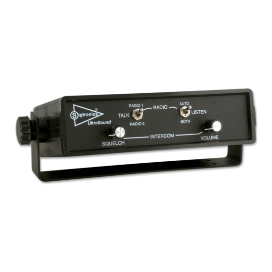
Sigtronics UltraSound Tactical Intercom System
INTRODUCTION
ATTENTION INSTALLER: To assure a trouble free installation,
please read these entire instructions through once before
beginning.
The Sigtronics UltraSound Tactical Intercom System, when used with
Sigtronics noise attenuating headsets provides the tactical transport
crew with clear, hands free, voice activated (VOX) intercom. The
system also allows full radio monitoring at all headset positions as
well as radio transmit capability from selected headsets via Push-
To-Talk (PTT) switches.
Applications: The unit is designed for tactical, rescue and mobile
command center vehicles.
S
igtronics
UT-4D, UT-4S, UT-6D, and UT-6S
INSTALLATION AND OPERATING INSTRUCTIONS
UT-4S
Specialists in "SOUND" Management
®
178 East Arrow Highway, San Dimas, CA 91773 (909) 305-9399
Voice Activated Intercom (VOX) feature allows "hands free" com-
munication between headsets connected to the UltraSound unit.
Start speaking and the intercom turns on instantly to relay your
message clearly to the other headsets. Stop talking and it turns off
to reduce background noise.
Up to Four Headset Positions can be connected to the UltraSound
unit models UT-4S and UT-4D. Up to six for models UT-6S and UT-6D.
More headset positions can be achieved by wiring additional jacks in
parallel. Only one headset, however, can be plugged into paralleled
jacks at one time. In the case of the Driver, he plugs his headset into
his jack while driving. He then unplugs and plugs into the Driver's
Auxiliary jack when he arrives on scene.
UT-4D
Advertisement
Table of Contents

Related Manuals for Sigtronics UT-4D


Summary of Contents for Sigtronics UT-4D
- Page 1 (VOX) intercom. The system also allows full radio monitoring at all headset positions as unit models UT-4S and UT-4D. Up to six for models UT-6S and UT-6D. well as radio transmit capability from selected headsets via Push- More headset positions can be achieved by wiring additional jacks in To-Talk (PTT) switches.
-
Page 2: Control Functions
Refer to the UltraSound Wiring Diagram. For UT-4S or UT-6S see Figure 4; for UT-4D or UT-6D see Figure 5. If you have The UT-6S is for single radio operations and can intercom up to six any installation questions or problems that are not addressed in this people at one time. - Page 3 Headset Jack Placement: It is assumed that it has already been determined which positions Sigtronics provides two ways to mount the headset jacks for the on the vehicle will have headsets. At this stage, it is helpful to have UltraSound unit: a headset handy to physically gauge the best place for a particular jack.
-
Page 4: Headset Jack
PTT switches. For the UT-4S For direct mounting of headset jacks on the vehicle panel you will and UT-4D models, this cable has a 12 pin connector with 10 wires. need to remove the jack from the jack box cover with a 1⁄2 inch For the UT-6S and UT-6D, there is a 15 pin connector and 13 wires. -
Page 5: Power Connections
They can be used on PTT switches is out of sight. It should be run behind vehicle panels positive ground vehicles only if a Sigtronics Positive Ground Adapter and/or up in the headliner. This will reduce the chance of personnel is used. - Page 6 NOTE 3 INTERCOM BARREL INTERCOM UNIT HEADSET JACK CREW #3 NOTE 3 UT-4D/6D (DUAL RADIO) WIRING DIAGRAM (15) YELLOW NOTE 3 PTT SWITCH NOTES: 1) CONNECT EITHER VIOLET WIRE TO THE RADIO SPEAKER HI OUTPUT. CONNECT (14) WHITE / BROWN...
- Page 7 3. The next step is to reconnect the green wire and do the electrical senger’s PTT switch and vise versa. noise test again to assure that you have fixed all possible noise problems. Ut-4 Ut-6 i SigtronicS igtronicS ltra oUnd ntercomS...
- Page 8 2. The other type of noise is that generated by equipment that uses the vehicle’s power. This type of noise is usually constant and does For dual radio units (UT-4D or UT-6D), hook up Radio 1 first and test not vary with engine rpm. It does, however, go away completely before moving on to Radio 2.
- Page 9 The last step is to set the Radio 1 Microphone Transmit Gain. Micro- phone Transmit Gain (labeled MIC XMIT GAIN) adjustment for the thing is OK for UT-4D / UT-6D units, skip to the “Radio 2 Hook Up” radio (or both radios for UT-4D, UT-6D) is also provided on the back section.
- Page 10 Microphone Transmit Gain Adjustments are the top set of the two located on the back of the UltraSound unit. The adjustment This completes the UltraSound installation. procedure is very similar to that of the Radio 1 Mic Transmit Gain Ut-4 Ut-6 i igtronicS ltra oUnd ntercomS SigtronicS...
-
Page 11: Radio Operation
(See below) For Dual Radio Units - UT-4D and UT-6D: Intercom operation and adjustment can be performed by the following procedure: The operation of the dual radio UltraSound units are identical to that of the single radio units except for the addition of radio selection: 1. -
Page 12: Ultrasound Specifications
1.667 1.667 0.2 DIA + 0.01 0.25 0.50 MOUNTING BRACKET BOTTOM VIEW Sigtronics UltraSound Intercom Typical Installation Dimensions 7-18-2011 UltraSound_Installation_Dimensions.pdf Sigtronics Installation Hot Line Number: 1-800-367-0977 ext. 8 igtronics Monday through Friday, 8:00 a.m. to 4:30 p.m. Pacific Time ®...
Need help?
Do you have a question about the UT-4D and is the answer not in the manual?
Questions and answers