Table of Contents
Advertisement
Quick Links
A V T E C H
E L E C T R O S Y S T E M S
L T D .
N A N O S E C O N D
W A V E F O R M
E L E C T R O N I C S
S I N C E
1 9 7 5
info@avtechpulse.com
Tel: 888-670-8729 (USA & Canada) or +1-613-686-6675 (Intl)
BOX 5120, LCD MERIVALE
http://www.avtechpulse.com/
Fax: 800-561-1970 (USA & Canada) or +1-613-686-6679 (Intl)
OTTAWA, CANADA K2C3H5
INSTRUCTIONS
MODELS AVO-6HZ-B
10 AMP / 110 VOLT
LASER DIODE DRIVER
WITH IEEE 488.2 AND RS-232 CONTROL
SERIAL NUMBER:
14040
Advertisement
Table of Contents

Related Manuals for Avtech AVO-6-B


Summary of Contents for Avtech AVO-6-B
- Page 1 A V T E C H E L E C T R O S Y S T E M S L T D . N A N O S E C O N D W A V E F O R M E L E C T R O N I C S S I N C E 1 9 7 5...
-
Page 2: Warranty
Avtech product is found to be defective, Avtech shall at its option repair or replace said defective item. This warranty does not apply to units which have been dissembled, modified or subjected to conditions exceeding the applicable specifications or ratings. -
Page 3: Table Of Contents
TABLE OF CONTENTS WARRANTY........................2 TECHNICAL SUPPORT....................2 TABLE OF CONTENTS....................3 INTRODUCTION.......................5 HIGH-VOLTAGE PRECAUTIONS..................6 SPECIFICATIONS......................7 REGULATORY NOTES....................8 FCC PART 18.......................... 8 EC DECLARATION OF CONFORMITY..................8 DIRECTIVE 2011/65/EU (RoHS).....................9 DIRECTIVE 2002/96/EC (WEEE)....................9 FIRMWARE LICENSING.......................10 INSTALLATION......................11 VISUAL CHECK........................11 POWER RATINGS........................ 11 CONNECTION TO THE POWER SUPPLY................11 PROTECTION FROM ELECTRIC SHOCK................12 ENVIRONMENTAL CONDITIONS..................13 LABVIEW DRIVERS...................... - Page 4 PCB 217A - RELAY DRIVER....................43 PCB 104G - KEYPAD / DISPLAY BOARD................44 MAIN WIRING, -P UNITS......................45 MAIN WIRING, -N UNITS......................46 MAIN WIRING, -PN UNITS....................47 PERFORMANCE CHECK SHEET.................48 Manual Reference: /fileserver2/officefiles/instructword/avo-6/AVO-6HZ-B,ed11.odt. Last modified November 16, 2020. Copyright © 2020 Avtech Electrosystems Ltd, All Rights Reserved.
-
Page 5: Introduction
INTRODUCTION The AVO-6HZ-B is a high performance, GPIB and RS232-equipped instrument capable of generating up to 10 A at repetition rates up to 100 kHz. The pulse width is variable from 50 ns to 50 us, and the duty cycle may be as high as 5%. Rise and fall times are fixed at less than 15 ns. -
Page 6: High-Voltage Precautions
4. Keep in mind that all cables, connectors, oscilloscope probes, and loads must have an appropriate voltage rating. Do not attempt any repairs on the instrument, beyond the fuse replacement procedures described in this manual. Contact Avtech technical support (see page 2 for contact information) if the instrument requires servicing. -
Page 7: Specifications
The standard solder terminals can be replaced by a plug-in or screw-in socket. See sockets: http://www.avtechpulse.com/laser-bias/avx-s1 for examples. Contact Avtech (info@avtechpulse.com) with your special device mounting requirement. Connectors, other: Power requirements: 100 - 240 Volts, 50 - 60 Hz Dimensions: Mainframe: 100mm x 430 mm x 375mm (3.9”... -
Page 8: Regulatory Notes
If interference is observed, check that appropriate well-shielded cabling is used on the output connectors. Contact Avtech (info@avtechpulse.com) for advice if you are unsure of the most appropriate cabling. Also, check that your load is adequately shielded. It may be necessary to enclose the load in a metal enclosure. -
Page 9: Directive 2011/65/Eu (Rohs)
< 1000 ppm (0.1% by mass) DIRECTIVE 2002/96/EC (WEEE) European customers who have purchased this equipment directly from Avtech will have completed a “WEEE Responsibility Agreement” form, accepting responsibility for WEEE compliance (as mandated in Directive 2002/96/EC of the European Union and local... -
Page 10: Firmware Licensing
Article 9 of Directive 2002/96/EC. Customers who have purchased Avtech equipment through local representatives should consult with the representative to determine who has responsibility for WEEE compliance. Normally, such responsibilities with lie with the representative, unless other arrangements (under Article 9) have been made. -
Page 11: Installation
INSTALLATION VISUAL CHECK After unpacking the instrument, examine to ensure that it has not been damaged in shipment. Visually inspect all connectors, knobs, liquid crystal displays (LCDs), and the handles. Confirm that a power cord, a GPIB cable, and two instrumentation manuals (this manual and the “Programming Manual for -B Instruments”) are with the instrument. -
Page 12: Protection From Electric Shock
5. Do not attempt any repairs on the instrument, beyond the fuse replacement procedures described in this manual. Contact Avtech technical support (see page 2 for contact information) if the instrument requires servicing. Service is to... -
Page 13: Environmental Conditions
6. no pollution or only dry, non-conductive pollution. LABVIEW DRIVERS A LabVIEW driver for this instrument is available for download on the Avtech web site, at http://www.avtechpulse.com/labview. A copy is also available in National Instruments' Instrument Driver Library at http://www.natinst.com/. -
Page 14: Fuses
FUSES This instrument contains four fuses. All are accessible from the rear-panel. Two protect the AC prime power input, and two protect the internal DC power supplies. The locations of the fuses on the rear panel are shown in the figure below: Fuses #1 and #2 Fuse #4 Fuse #3... -
Page 15: Dc Fuse Replacement
DC FUSE REPLACEMENT The DC fuses may be replaced by inserting the tip of a flat-head screwdriver into the fuse holder slot, and rotating the slot counter-clockwise. The fuse and its carrier will then pop out. FUSE RATINGS The following table lists the required fuses for models with the -P or -N options: Recommended Replacement Part Nominal Fuses... -
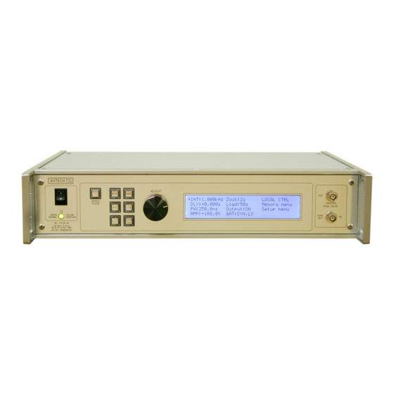
Page 16: Front Panel Controls
FRONT PANEL CONTROLS 1. POWER Switch . This is the main power switch. When turning the instrument on, there is normally a delay of 10 seconds before anything is shown on the main display, as the internal operating system boots up. If the main menu does not appear after 30 seconds, turn off the instrument and leave it off for at least 60 seconds before applying power again. - Page 17 5. KEYPAD . Control Name Function MOVE This moves the arrow pointer on the display. CHANGE This is used to enter the submenu, or to select the operating mode, pointed to by the arrow pointer. ×10 If one of the adjustable numeric parameters is displayed, this increases the setting by a factor of ten.
-
Page 18: Rear Panel Controls
REAR PANEL CONTROLS GATE TRIG CONTROL RS-232 GPIB Note: some connectors may be in different positions than shown above, depending on the exact combination of options ordered. 1. AC POWER INPUT . An IEC-320 C14 three-pronged recessed male socket is provided on the back panel for AC power connection to the instrument. - Page 19 width tracks the pulse width on this input, or the output pulse width can be set independently. 6. GPIB Connector . A standard GPIB cable can be attached to this connector to allow the instrument to be computer-controlled. See the “Programming Manual for -B Instruments”...
-
Page 20: General Information
GENERAL INFORMATION AMPLITUDE CONTROL The AVO-6HZ-B consists of two parts, the mainframe and the output module. The mainframe is a voltage pulser, which generates up to 110V (V The fan-cooled output module contains a 11Ω (±10%) series resistance (capable of dissipating up to 50 Watts of average power), and packaged diodes may be soldered to the output terminals of this module. -
Page 21: Monitor Option
Alternatively, a fast current probe may be used to monitor the current waveform. Factory testing is conducted using a Tektronix CT2 or Pearson 2878 current transformer. (This technique tends to introduce less waveform distortion than the sensing resistor method. However, AC-couped current probes such as the CT2 will not be able to operate at pulse widths of more than a few microseconds. -
Page 22: Basic Test Arrangement - With Output Module
To fully test the instrument, and for normal operation, the output module must be connected as shown below: Diode (device under test), oriented for positive operation. 6-foot DB-9 Reverse for negative operation. control cable AVTECH AVO-6HZ-T Tektronix CT2 current probe or OUTPUT AVO-6HZ-B Pearson 2878 current transformer MODULE... -
Page 23: Sma Option
This alternative test arrangement is shown below: Diode (device under test), 6-foot DB-9 oriented for positive operation. control cable AVTECH AVO-6HZ-T Reverse for negative operation. OUTPUT AVO-6HZ-B MODULE... - Page 24 oscilloscopes or other measurement systems. When the delay is set to a positive value the SYNC pulse precedes the OUT pulse. When the delay is set to a negative value the SYNC pulse follows the OUT pulse. These pulses are illustrated below, assuming internal triggering and a positive delay: 100 ns, FIXED SYNC OUT (generated by the...
-
Page 25: Trigger Modes
> 50 ns TRIG TTL LEVELS (external input) (0V and 3V-5V) PROPAGATION DELAY (FIXED) 100 ns, FIXED SYNC OUT 3V, FIXED DELAY > 0 PULSE WIDTH AMPLITUDE, VARIABLE MAIN OUTPUT As before, if the delay is negative, the order of the SYNC and OUT pulses is reversed. The delay, pulse width, and frequency (when in the internal mode), of the OUT pulse can be varied with front panel controls or via the GPIB or RS-232 computer interfaces. - Page 26 panel gate menu or the appropriate programming commands. This input can also be set to act synchronously or asynchronously. When set to asynchronous mode, the GATE will disable the output immediately. Output pulses may be truncated. When set to synchronous mode, the output will complete the full pulse width if the output is high, and then stop triggering.
-
Page 27: Operational Check
OPERATIONAL CHECK This section describes a sequence to confirm the basic operation of the instrument. It should be performed after receiving the instrument. It is a useful learning exercise as well. Before proceeding with this procedure, finish read this instruction manual thoroughly. Then read the “Local Control”... - Page 28 a)Press the MOVE button until the arrow pointer is pointing at the delay menu item. b)Press the CHANGE button. The delay submenu will appear. Rotate the ADJUST knob until the delay is set at 1 us. c)The arrow pointer should be pointing at the “Normal” choice. If it is not, press MOVE until it is.
- Page 29 (Some current probes may require a 50 Ohm termination). Set the oscilloscope to trigger externally. Diode (device under test), oriented for positive operation. 6-foot DB-9 Reverse for negative operation. control cable AVTECH AVO-6HZ-T Tektronix CT2 current probe or OUTPUT AVO-6HZ-B Pearson 2878 current transformer MODULE...
- Page 30 d)Press CHANGE to return to the main menu. 5.To set the pulse width to 1 us: a)Press the MOVE button until the arrow pointer is pointing at the pulse width menu item. b)Press the CHANGE button. The pulse width submenu will appear. Rotate the ADJUST knob until the pulse width is set at 1 us.
-
Page 31: Programming Your Pulse Generator
PROGRAMMING YOUR PULSE GENERATOR KEY PROGRAMMING COMMANDS The “Programming Manual for -B Instruments” describes in detail how to connect the pulse generator to your computer, and the programming commands themselves. A large number of commands are available; however, normally you will only need a few of these. -
Page 32: All Programming Commands
ALL PROGRAMMING COMMANDS For more advanced programmers, a complete list of the available commands is given below. These commands are described in detail in the “Programming Manual for -B Instruments”. (Note: this manual also includes some commands that are not implemented in this instrument. - Page 33 :SOURce INTernal | EXTernal | MANual | HOLD | IMMediate *CLS [no query form] *ESE <numeric value> *ESR? [query only] *IDN? [query only] *OPC *SAV 0 | 1 | 2 | 3 [no query form] *RCL 0 | 1 | 2 | 3 [no query form] *RST [no query form]...
-
Page 34: Mechanical Information
Always disconnect the power cord before opening the instrument. There are no user-adjustable internal circuits. For repairs other than fuse replacement, please contact Avtech (info@avtechpulse.com) to arrange for the instrument to be returned to the factory for repair. Caution: High voltages are present inside the instrument during normal operation. -
Page 35: Maintenance
MAINTENANCE REGULAR MAINTENANCE This instrument does not require any regular maintenance. On occasion, one or more of the four rear-panel fuses may require replacement. All fuses can be accessed from the rear panel. See the “FUSES” section for details. CLEANING If desired, the interior of the instrument may be cleaned using compressed air to dislodge any accumulated dust. -
Page 36: Wiring Diagrams
WIRING DIAGRAMS WIRING OF AC POWER M a ins circuits - ha z ard ou s live . A3 - BLACK Do not attem pt any repairs on this instrument POWER SWITCH SW325-ND (CW INDUSTRIES G RS-4022-0013) bey ond the fuse replacement procedures described NORMALLY: ECP180PS24 in the m anual. -
Page 37: Wiring Of Dc Power
WIRING OF DC POWER M OUNT WIT H 1/2" ST ANDO FFS P1, N1 = 15000uF, 35V x 2 R1,R2 (O N BOT T OM ): 1.8K O Y CHS GND G RN T O AC/DC CONVERT ER PCB 179B, TRIM MED EXT RA LINES O N HIG H-PO WER ALL UNIT S... -
Page 38: Pcb 158R5 - Low Voltage Power Supply
PCB 158R5 - LOW VOLTAGE POWER SUPPLY... -
Page 39: Pcb 197J - High Voltage Discharge Board
PCB 197J - HIGH VOLTAGE DISCHARGE BOARD... -
Page 40: Pcb 183A-S And 183A-P Capacitor Banks
PCB 183A-S AND 183A-P CAPACITOR BANKS 183A-S (SERIES CAPACIT OR BANK) 7 2 00 K -ND, Mfg . 7 2 0 0, 4-4 0 th read stando ff 3 /8" HV + GN D 7 2 00 K -ND, Mfg . 7 2 0 0, 4-4 0 th read stando ff 3 /8" X1 1 7 2 00 K -ND, Mfg . -
Page 41: Pcb 156D - Polarity Control Board
PCB 156D - POLARITY CONTROL BOARD R2 8 R2 3 "UV- ON" IS HIGH IF: 1) "UV+ HIGH" IS LOW, AND +1 5 V VC C VC C 2) "POL" IS LOW. R1 9 0 . 1 u F R1 2 R1 6 5 6 K SU RF AC E MOUN T , ON B OTTOM. -
Page 42: Pcb 94H - Alarm Board
PCB 94H - ALARM BOARD... -
Page 43: Pcb 217A - Relay Driver
PCB 217A - RELAY DRIVER K E Y S T O N E 6 2 1 B R A C K E T P S 7 1 0 A - 1 A P S 7 1 0 A - 1 A K E Y S T O N E 6 2 1 B R A C K E T 1 . -
Page 44: Pcb 104G - Keypad / Display Board
PCB 104G - KEYPAD / DISPLAY BOARD... -
Page 45: Main Wiring, -P Units
MAIN WIRING, -P UNITS USE 1/2" ST ANDOFFS +15V NSY N4-N6: UNUSED P4-P6: 1500uF,160V VPRF R9-R10: UNUSED OP1B M AIN BOARD, PCB 295F VSPARE R7-R8: 18K OY SYNC PG-P CONN1 PCB 183A-P SYNC O LIM EX +15V ON/OFF +5V ON/OFF M AIN OUT SYNC OUT EXT TRIG... -
Page 46: Main Wiring, -N Units
MAIN WIRING, -N UNITS -T N T OPTION ONL Y CO NN 1 VC C LED M O UN T L-CO M EC F5 0 4 -SC 5 L-CO M TRD 855S IG-1 C AB LE US E 1/2" S TAN DOFFS +1 5 V GR N P4 -P 6: U NU SE D... -
Page 47: Main Wiring, -Pn Units
MAIN WIRING, -PN UNITS US E 1/2" ST ANDOFFS P1-P3, N1-N3: 18 00uF,160V POS OLO R7-R10: 100K OLO GND PCB 1 83A-P 1/8 C2 4-P1 25, WITH PCB 1 97G 1/8 C2 4-N1 25, WITH PCB 197G 197G 197G POS V ERSION, HAS: NEG VERSION, HAS: D2,4,5,7 NORM ORIENT. -
Page 48: Performance Check Sheet
PERFORMANCE CHECK SHEET...
Need help?
Do you have a question about the AVO-6-B and is the answer not in the manual?
Questions and answers