Table of Contents
Advertisement
Quick Links
P.O. BOX 265
OGDENSBURG, NY
U.S.A. 13669-0265
A V T E C H
TEL: 888-670-8729 (USA & Canada) or +1-613-686-6675 (Intl)
FAX: 800-561-1970 (USA & Canada) or +1-613-686-6679 (Intl)
info@avtechpulse.com
INSTRUCTIONS
MODEL AVIR-1-B
0 TO 200 VOLT
HIGH PERFORMANCE PULSE GENERATOR
WITH IEEE 488.2 AND RS-232 CONTROL
SERIAL NUMBER: ____________
E L E C T R O S Y S T E M S
N A N O S E C O N D
W A V E F O R M
S I N C E
-
http://www.avtechpulse.com/
E L E C T R O N I C S
1 9 7 5
BOX 5120, LCD MERIVALE
X
OTTAWA, ONTARIO
CANADA
L T D .
K2C 3H4
Advertisement
Table of Contents

Related Manuals for Avtech AVIR-1-B


Summary of Contents for Avtech AVIR-1-B
- Page 1 BOX 5120, LCD MERIVALE OGDENSBURG, NY FAX: 800-561-1970 (USA & Canada) or +1-613-686-6679 (Intl) OTTAWA, ONTARIO U.S.A. 13669-0265 CANADA K2C 3H4 info@avtechpulse.com http://www.avtechpulse.com/ INSTRUCTIONS MODEL AVIR-1-B 0 TO 200 VOLT HIGH PERFORMANCE PULSE GENERATOR WITH IEEE 488.2 AND RS-232 CONTROL SERIAL NUMBER: ____________...
-
Page 2: Warranty
Avtech product is found to be defective, Avtech shall at its option repair or replace said defective item. This warranty does not apply to units which have been dissembled, modified or subjected to conditions exceeding the applicable specifications or ratings. -
Page 3: Table Of Contents
TABLE OF CONTENTS WARRANTY........................2 TECHNICAL SUPPORT....................2 TABLE OF CONTENTS....................3 INTRODUCTION.......................5 AVAILABLE OPTIONS......................5 SPECIFICATIONS......................6 REGULATORY NOTES....................7 FCC PART 18.......................... 7 EC DECLARATION OF CONFORMITY..................7 DIRECTIVE 2002/95/EC (RoHS).....................8 DIRECTIVE 2002/96/EC (WEEE)....................8 AC POWER SUPPLY REGULATORY NOTES...............9 INSTALLATION......................10 VISUAL CHECK........................10 POWER RATINGS........................10 CONNECTION TO THE POWER SUPPLY................10 PROTECTION FROM ELECTRIC SHOCK................11 ENVIRONMENTAL CONDITIONS..................12... - Page 4 PCB 104D - KEYPAD / DISPLAY BOARD, 1/3..............39 PCB 104D - KEYPAD / DISPLAY BOARD, 2/3..............40 PCB 104D - KEYPAD / DISPLAY BOARD, 3/3..............41 MAIN WIRING........................42 PERFORMANCE CHECKSHEET...................43 Manual Reference: /fileserver2/officefiles/instructword/avir/AVIR-1-B,edition1.odt. Last modified February 29, 2012. Copyright © 2012 Avtech Electrosystems Ltd, All Rights Reserved.
-
Page 5: Introduction
A 50 Ohm load is required for proper operation. The output stage may be damaged if the output is not terminated into a 50Ω load. The AVIR-1-B is a highly flexible instrument. Aside from the internal trigger source, it can also be triggered or gated by external TTL-level signals. A front-panel pushbutton or a computer command can also be used to trigger the instrument. -
Page 6: Specifications
SPECIFICATIONS Model: AVIR-1-B Amplitude 3,4,5,9 0 to 200 Volts (50Ω load required) Pulse width (FWHM) 2 - 5 ns Max. rise time (20%-80%): 1 ns Max. fall time (80%-20%): 1.8 ns PRF: 0 to 50 kHz Polarity Positive or negative or both (specify) GPIB and Standard on -B units. -
Page 7: Regulatory Notes
If interference is observed, check that appropriate well-shielded cabling is used on the output connectors. Contact Avtech (info@avtechpulse.com) for advice if you are unsure of the most appropriate cabling. Also, check that your load is adequately shielded. It may be necessary to enclose the load in a metal enclosure. -
Page 8: Directive 2002/95/Ec (Rohs)
Directive 2002/96/EC categories 1-7 and 10, as stated in the "Article 2 - Scope" section of Directive 2002/95/EC. DIRECTIVE 2002/96/EC (WEEE) European customers who have purchased this equipment directly from Avtech will have completed a “WEEE Responsibility Agreement” form, accepting responsibility for WEEE compliance (as mandated in Directive 2002/96/EC of the European Union and local laws) on behalf of the customer, as provided for under Article 9 of Directive 2002/96/EC. -
Page 9: Ac Power Supply Regulatory Notes
AC POWER SUPPLY REGULATORY NOTES This instrument converts the AC input power to the +24V DC voltage that powers the internal circuitry of this instrument using a Tamura AAD130SD-60-A switching power supply. According to the manufacturer, the Tamura AAD130SD-60-A has the following certifications: UL60950-1 IEC60950 -1... -
Page 10: Installation
INSTALLATION VISUAL CHECK After unpacking the instrument, examine to ensure that it has not been damaged in shipment. Visually inspect all connectors, knobs, liquid crystal displays (LCDs), and the handles. Confirm that a power cord, a GPIB cable, and two instrumentation manuals (this manual and the “Programming Manual for -B Instruments”) are with the instrument. -
Page 11: Protection From Electric Shock
5. Do not attempt any repairs on the instrument, beyond the fuse replacement procedures described in this manual. Contact Avtech technical support (see page 2 for contact information) if the instrument requires servicing. Service is to... -
Page 12: Environmental Conditions
6. no pollution or only dry, non-conductive pollution. LABVIEW DRIVERS A LabVIEW driver for this instrument is available for download on the Avtech web site, at http://www.avtechpulse.com/labview. A copy is also available in National Instruments' Instrument Driver Library at http://www.natinst.com/. -
Page 13: Fuses
FUSES This instrument contains four fuses. All are accessible from the rear-panel. Two protect the AC prime power input, and two protect the internal DC power supplies. The locations of the fuses on the rear panel are shown in the figure below: Fuses #1 and #2 Fuse #4 Fuse #3... -
Page 14: Dc Fuse Replacement
DC FUSE REPLACEMENT The DC fuses may be replaced by inserting the tip of a flat-head screwdriver into the fuse holder slot, and rotating the slot counter-clockwise. The fuse and its carrier will then pop out. FUSE RATINGS The following table lists the required fuses: Recommended Replacement Part Nominal Fuses... -
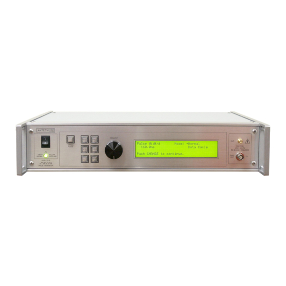
Page 15: Front Panel Controls
FRONT PANEL CONTROLS 1. POWER Switch . This is the main power switch. When turning the instrument on, there may be a delay of several seconds before the instrument appears to respond. 2. OVERLOAD Indicator . When the instrument is powered, this indicator is normally green, indicating normal operation. - Page 16 which lists the key adjustable parameters and their current values. The “Programming Manual for -B Instruments” describes the menus and submenus in detail. 6. KEYPAD . Control Name Function MOVE This moves the arrow pointer on the display. CHANGE This is used to enter the submenu, or to select the operating mode, pointed to by the arrow pointer.
-
Page 17: Rear Panel Controls
REAR PANEL CONTROLS GRN=LNK GATE YEL=ACT TRIG RS-232 GPIB 1. AC POWER INPUT . An IEC-320 C14 three-pronged recessed male socket is provided on the back panel for AC power connection to the instrument. One end of the detachable power cord that is supplied with the instrument plugs into this socket. - Page 18 “Programming Manual for -B Instruments” for more details on RS-232 control. 8. LAN Connector and Indicator . (Optional feature. Present on -TNT units only.) The -TNT option "Internet-enables" Avtech pulse generators by adding this standard Ethernet port to the rear panel, in addition to the IEEE-488.2 GPIB and RS-232 ports normally found on "-B"...
-
Page 19: General Information
GENERAL INFORMATION BASIC PULSE CONTROL This instrument can be triggered by its own internal clock or by an external TTL trigger signal. In either case, two output channels respond to the trigger: OUT and SYNC. • OUT. This is the main output. The maximum output voltage is 200V. •... -
Page 20: Trigger Modes
The next figure illustrates the relationship between the signal when an external TTL- level trigger is used: > 50 ns TRIG TTL LEVELS (external input) (0V and 3V-5V) PROPAGATION DELAY (FIXED) 100 ns, FIXED SYNC OUT 3V, FIXED DELAY > 0 PULSE WIDTH AMPLITUDE, VARIABLE... -
Page 21: Gating Modes
WARNING: The output stage may be damaged if triggered by an external signal at a pulse repetition frequency greater than 50 kHz. GATING MODES Triggering can be suppressed by a TTL-level signal on the rear-panel GATE connector. The instrument can be set to stop triggering when this input high or low, using the front- panel gate menu or the appropriate programming commands. -
Page 22: Optional Features
OPTIONAL FEATURES RACK MOUNTING, -R5 OPTION A rack mounting kit is available. The -R5 rack mount kit may be installed after first removing the one Phillips screw on the side panel adjacent to the front handle. DC OFFSET, -OS OPTION A DC offset can be added to the output signal by applying a DC voltage to the rear-panel OS connector. -
Page 23: Protecting Your Instrument
PROTECTING YOUR INSTRUMENT TURN OFF INSTRUMENT WHEN NOT IN USE The lifetime of the switching elements in the pulse generator module is proportional to the running time of the instrument. For this reason the prime power to the instrument should be turned off when the instrument is not in use. In the case of failure, the switching elements are easily replaced following the procedure described in a following section. -
Page 24: Operational Check
A 50 Ohm load is required for proper operation. The output stage may be damaged if the output is not terminated into a 50Ω load. The AVIR-1-B output may be observed using either a high-speed sampling oscilloscope, or a slower real-time oscilloscope. To accurately observe these rising and falling edges, a sampling oscilloscope with a bandwidth of 10 GHz is required. - Page 25 Set the oscilloscope to trigger externally with the vertical setting at 100 mV/div for sampling oscilloscopes, or 100 V/div for real-time scopes, and the horizontal setting at 10 ns/div. 2. Turn on the AVIR-1-B. The main menu will appear on the LCD.
- Page 26 3. To set the AVIR-1-B to trigger from the internal clock at a PRF of 10 kHz: a) The arrow pointer should be pointing at the frequency menu item. If it is not, press the MOVE button until it is.
- Page 27 c) Press MOVE until the arrow pointer is pointing at the “ON” choice. d) Press CHANGE to return to the main menu. 8. To change the output amplitude: a) Press the MOVE button until the arrow pointer is pointing at the amplitude menu item.
-
Page 28: Programming Your Pulse Generator
PROGRAMMING YOUR PULSE GENERATOR KEY PROGRAMMING COMMANDS The “Programming Manual for -B Instruments” describes in detail how to connect the pulse generator to your computer, and the programming commands themselves. A large number of commands are available; however, normally you will only need a few of these. -
Page 29: All Programming Commands
ALL PROGRAMMING COMMANDS For more advanced programmers, a complete list of the available commands is given below. These commands are described in detail in the “Programming Manual for -B Instruments”. (Note: this manual also includes some commands that are not implemented in this instrument. - Page 30 :[TYPE] EVEN | ODD | NONE :SBITS 1 | 2 :ERRor :[NEXT]? [query only] :COUNT? [query only] :VERSion? [query only] TRIGger: :SOURce INTernal | EXTernal | MANual | HOLD | IMMediate *CLS [no query form] *ESE <numeric value> *ESR? [query only] *IDN? [query only] *OPC...
-
Page 31: Mechanical Information
There are no user-adjustable internal circuits. For repairs other than fuse replacement, please contact Avtech (info@avtechpulse.com) to arrange for the instrument to be returned to the factory for repair. Service is to be performed solely by qualified service personnel. -
Page 32: Maintenance
MAINTENANCE REGULAR MAINTENANCE This instrument does not require any regular maintenance. On occasion, one or more of the four rear-panel fuses may require replacement. All fuses can be accessed from the rear panel. See the “FUSES” section for details. CLEANING If desired, the interior of the instrument may be cleaned using compressed air to dislodge any accumulated dust. -
Page 33: Wiring Diagrams
WIRING DIAGRAMS WIRING OF AC POWER M a in s c ir c u i ts - h a z a r d o u s liv e . D o n o t a tte m p t a n y r e p a i r s o n th is in s t r u m e n t b e y o n d t h e fu s e r e p l a c e m e n t p r o c e d u r e s d e s c r i b e d in th e m a n u a l . -
Page 34: Pcb 158J - Low Voltage Dc Power Supply, 1/3
PCB 158J - LOW VOLTAGE DC POWER SUPPLY, 1/3 p cb 1 58 j_o v p p cb 1 58 j_o v p .s ch +1 5V +1 5V +1 5V GN D GN D P-OU T # 1 P-OU T # 1 -1 5 V -1 5 V -1 5 V... -
Page 35: Pcb 158J - Low Voltage Dc Power Supply, 2/3
PCB 158J - LOW VOLTAGE DC POWER SUPPLY, 2/3 8 3 08 3 5 FUSEHO LDER 6 4 04 4 5 -6 TEST-LOO P TEST-LOO P S1 A S1 B, OR D C S2 A, O R DC S2 B 4 3 4- 13 -1 0 0 M C2 0 C1 9... -
Page 36: Pcb 158J - Low Voltage Dc Power Supply, 3/3
PCB 158J - LOW VOLTAGE DC POWER SUPPLY, 3/3 BLEED ER S D1 1 R2 1 CAPBANK 3 3 0 OY 1 .5 K O Y 1 N4 9 3 7 C2 3 1 0 00 u F,3 5 V (P5 16 9 -ND ) SHO RTS OU T B ASE WHEN C HAR GING. -
Page 37: Pcb 168B - High Voltage Dc Power Supply
PCB 168B - HIGH VOLTAGE DC POWER SUPPLY HV WA RN ING HV WA RN ING 1 N4 9 3 7 1 N4 9 3 7 6 4 04 4 5 -2 6 4 04 4 5 -2 1 N4 9 3 7 1 N4 9 3 7 1 0 0 OY R1 0... -
Page 38: Pcb 206A - Prf Limiter
PCB 206A - PRF LIMITER 2 S E C E R R O R F L A G U 1 B K E Y S T O N E 6 2 1 B R A C K E T V C C C L R C e x t R e x t / C e x t... -
Page 39: Pcb 104D - Keypad / Display Board, 1/3
PCB 104D - KEYPAD / DISPLAY BOARD, 1/3 AH E10 G- ND, Mfg 49 9 9 10 -1 , 1 0 pin straig h t h ead er LCD-BUTT LCD-BUTT.SCH GN D GN D VCC-LED VCC-LED BACKLIG HT BACKLIG HT ENCOD ER ENCOD ER.SCH I2 C_ INT... -
Page 40: Pcb 104D - Keypad / Display Board, 2/3
PCB 104D - KEYPAD / DISPLAY BOARD, 2/3 U4 A C1 0 PIN3 2 .2 u F C1 5 C1 3 1 5 K MM7 4H C1 4 N 0 .1 u F 0 .1 u F 0 .1 u F 0 .1 u F GN D U4 B... -
Page 41: Pcb 104D - Keypad / Display Board, 3/3
PCB 104D - KEYPAD / DISPLAY BOARD, 3/3 2 2 uF 0 .1 u F GN D IN T GN D PAD 3 PAD 4 PCF8 5 7 4A PN LED+ LED- U1 A U1 C MM7 4H C1 4 N MM7 4H C1 4 N 2 .7 OH M, 2 W U1 B... -
Page 42: Main Wiring
MAIN WIRING - TN T O P T I O N O N L Y 1 / 2 A 2 4 - P 3 0 - M E , W I T H P C B 1 6 8 U V 1 C O N N 1 V C C L E D M O U N T L - C O M E C F 5 0 4 - S C 5... -
Page 43: Performance Checksheet
PERFORMANCE CHECKSHEET...
Need help?
Do you have a question about the AVIR-1-B and is the answer not in the manual?
Questions and answers