
Related Manuals for NewArc Mig500


Summary of Contents for NewArc Mig500
- Page 1 Newcastle Upon Tyne Powered by Tel. 0191 295 0111 sales@newarc.co.uk ® Newarc MIG500 Operational Manual NA9910210...
- Page 2 The RoHS Directive 2011/65/EU, entering into force 2 January 2013 Type of Equipment Welding power source for MIG Brand name or trade mark Newarc Type designation etc. MIG 500 Manufacturer or his authorised representative established within the EEA Name, address, telephone no...
- Page 3 Safety Guidelines These general safety guides cover both arc welding machines and plasma cutting machines unless otherwise noted. The equipment must only be used for the purpose it was designed for. Using it in any other way could result in damage or injury and in breach of the safety rules. Only suitably trained and competent persons should use the equipment.
- Page 4 Wear suitable protective flame resistant clothing. The sparks and spatter from welding, hot work pieces, and hot equipment can cause fires and burns. Welding on closed containers, such as tanks, drums, or pipes, can cause them to explode. Accidental contact of electrode to metal objects can cause arcs, explosion, overheating, or fire.
- Page 5 LF Declaration Consult the data plate on the equipment for the power supply requirements. Due to the elevated absorbency of the primary current from the power supply network, high power systems affect the quality of power provided by the network. Consequently, connection restrictions or maximum impedance requirements permitted by the network at the public network connection point must be applied to these systems.
-
Page 6: Table Of Contents
Contents Preface General Introduction Technical Specifications Overview of Machine Installation Operation Start up Display Standard Display Functions Standard Display Functions MIG Standard Display Functions User Menu Standard Display Functions Errors Fault Finding Welding Problems Maintenance Warranty Parts MIG 500... -
Page 7: Preface
This operating manual contains important information on the use, maintenance and safety of your Newarc product. Please read the manual carefully before using the equipment for the first time. For your own safety and that of your working environment, pay particular attention to the safety instructions in the manual. -
Page 8: Introduction
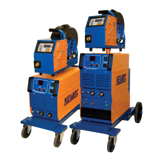
Due to the high efficiency and power factor these units provide energy and cost saving solutions. The MIG500 Power Source is capable of MIG welding when used with a peripheral wire feed unit. Features •... -
Page 9: Technical Specifications
1.3 Technical Specifications Newarc MIG500 Power voltage (V) 380-480 Volts 3 Phase 50/60Hz Input Current Power Consumption 18.5 KVA Recommended Mains Fuse 32A slow blow or type C MCB Variable 4 x 4.0mm² flexible cable Mains Cable Power Factor 0.95... -
Page 10: Overview Of Machine
1.4 Overview of Machine SECTION 4 — OPERATION 4.1 Description of controls Front View Mode Indication - LEDs to display welding mode (MIG 400 power source only the MIG LED will function). Panel layout 1. Mode Indication 2. Rotary encoder - Adjusts the machines functional parameters and user settings, as well as output current in CC mode or Voltage in CV mode (when not controlled remotely). - Page 11 5. Inductance control Operates in MIG mode only. This control alters the response time of the power source and is generally used in short circuit dip transfer welding. Too little inductance will result in excessive spatter and too much inductance will not allow the welding current to rise fast enough causing the electrode to stub into the base metal.
-
Page 12: Installation
2. Installation Unpacking Check the packaging for any signs of damage. Carefully remove the machine and retain the packaging until the installation is complete. Positioning of the machine Place the machine on a firm, dry and level surface. Where possible, do not allow dust or other impurities to enter the machines cooling air flow. -
Page 13: Operation
3. Operation Front panel operation This design is based on microprocessor technology and allows to implement set of functions previously not available in Newarc inverters: • Encoder based function control - digital settings • Hot start control • Operation time control •... -
Page 14: Start Up Display
By default both the current and voltage displays show four dashes when not welding. When current flows, panel shows actual current and voltage on display. Every other function is accessible by short pressing encoder down and turning encoder anti- or clockwise for the correct value. -
Page 15: Standard Display Functions Mig
Default function Conditional function Additional function A or V letters are dimmed on display for better recognising read value of voltage and current 3.3 Standard Display Functions MIG 4.2.6 Standard display functions: MIG Mode Actual Current and Voltage Set Voltage Welding Time Duration Mode Change (When welding) -
Page 16: Standard Display Functions User Menu
SECTION 4 — OPERATION 3.4 Standard Display Functions User Configuration Menu 4.2.7 Standard display functions: USER Configuration Menu Reachable after long encoder button press (~3s) and indicated by flashing 3 LED diodes To save changes, press long encoder button (~3s) C.U. -
Page 17: Standard Display Functions Errors
SECTION 4 — OPERATION 3.5 Standard Display Functions Errors 4.2.10 Standard display functions: Errors Front Panel Errors ERROR 0 E.r.8.0. Over temperature fault Internal temperature too high -.o.t.-. -OT- Microprocessor internal reference volt- age low - probably there is negative (<- Error 1 E.r.8. -
Page 18: Fault Finding
6.3A ‘slow blow’ . Any welding problems not covered above must be brought to the attention of a qualified Welding Engineer, if the problem still persists have the R4000/ R5000 checked by a trained Newarc service engineer. MIG 500... -
Page 19: Welding Problems
WFU instruction manual. Any welding problems not covered above must be brought to the attention of a qualified Welding Engineer, if the problem still persists have the R4000/R5000 checked by a trained Newarc service engineer. MIG 500... -
Page 20: Maintenance
5. Maintenance Note! All Electric shocks are potentially fatal, switch off the machine and unplug from the mains supply before carrying out any maintenance work. It is very important that the Wire feed unit is regularly maintained. The amount of use and the working environment must be taken into account when scheduling the maintenance periods. -
Page 21: Warranty
Newarc Ltd warrants that its goods and services are guaranteed to meet the specific performance under the stated conditions of use. Newarc cannot be held responsible for general wear and tear or for failure occurring due to misuse or abuse arising out of circumstances outside the stated condi-tions of use. -
Page 22: Parts
7. Parts SECTION 7—PARTS BREAKDOWN 7.1 - Component Locations MIG400 Power Source MIG 500... - Page 23 SECTION 7—PARTS BREAKDOWN 7.1 - Component Locations MIG400 Power Source MIG 500...
- Page 24 Ordering information Item Description Part number NAM01393 Front bridge handles (2 per machine) Lid Bridge handle (2 per machine) NAM01084 24mm diameter knob NAM01609 NAM01610 20mm diameter knob (3 per machine) NAM70069A On/Off switch NAM90762 Remote socket assembly EW7095PSW 70/90 panel mount Dix socket (2 per machine) NAM70071 Mains Switch —...
- Page 25 Notes MIG 500...
- Page 26 MIG 500...
- Page 27 MIG 500...
- Page 28 Unit 1, Whitehouse Industrial Estate, Whitehouse Road Newcastle upon Tyne NE15 6LN Tel: +44 (0)191 295 0111| Email: sales@newarc.co.uk | www.newarc.co.uk Powered by MIG 500 www.newarc.co.uk ®...
Need help?
Do you have a question about the Mig500 and is the answer not in the manual?
Questions and answers