Advertisement
Quick Links
Model/Modelo/Modèle
65430LF-▲
65430LF-▲-ECO
Series/Series/Seria
Virage
®
Write purchased model number here.
Escriba aquí el número del modelo comprado.
Inscrivez le numéro de modèle ici.
▲ Specify Finish / Especifíque el Acabado / Précisez le Fini
You may need/Usted puede necesitar/Articles dont vous pouvez avoir besoin:
For easy installation of your Brizo
faucet you will need:
• To READ ALL the instructions completely before
beginning.
• To READ ALL warnings, care, and
maintenance information.
• To purchase the correct water supply hook-up.
Para instalación fácil de su llave
Brizo
usted necesitará:
®
• LEER TODAS las instrucciones completamente
antes de empezar.
• LEER TODOS los avisos, cuidados, e
información de mantenimiento.
• Comprar las conexiones correctas para el
suministro de agua.
Pour installer votre robinet Brizo
facilement, vous devez:
• LIRE TOUTES les instructions avant de débuter;
• LIRE TOUS les avertissements ainsi que toutes
les instructions de nettoyage et d'entretien;
• Acheter le bon nécessaire de raccordement.
www.brizo.com
86534
2.5 mm
(3/32")
®
®
86534
1
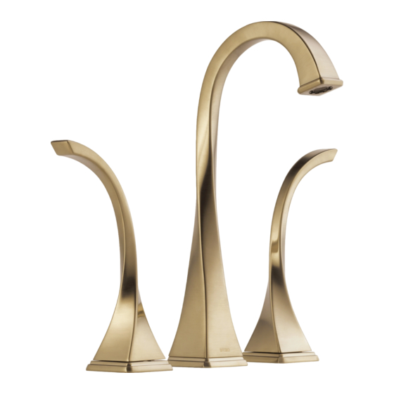
TWO HANDLE DECK VESSEL
WIDESPREAD LAVATORY FAUCETS
LLAVES DE AGUA DE DOS MANIJAS
PARA LAVAMANOS Y ARTESAS
ROBINETS À DEUX POIGNÉES
POUR LAVABO ET CUVETTE
?
4/01/16
Rev. C
Advertisement

Related Manuals for Brizo Virage 65430LF ECO Series


Summary of Contents for Brizo Virage 65430LF ECO Series
- Page 1 Inscrivez le numéro de modèle ici. ▲ Specify Finish / Especifíque el Acabado / Précisez le Fini You may need/Usted puede necesitar/Articles dont vous pouvez avoir besoin: 2.5 mm (3/32") For easy installation of your Brizo ® faucet you will need: • To READ ALL the instructions completely before beginning. • To READ ALL warnings, care, and maintenance information.
- Page 2 1 1/8" (29 mm) 1 1/8" Diameter (29 mm) Min. Diameter Min. INSTALLATION OF VALVE ASSEMBLIES & TRIM Note: When drilling holes for supply valves, it is recommended that hole size must be a minimum of 1 1/8" (29 mm). Look for a blue label or dot on cold valve assembly and red INSTALLATION OF SPOUT label or dot on hot valve assembly and install them on appropriate side. Note: When drilling mounting holes for the spout it is recommended that Assemble mounting parts to side valve (1), nut (2) & washer (3) making the hole size must be a minimum of 1 1/8"...
- Page 3 Make sure valve is in off position. Place glide ring (1) into the groove in the bottom of handle (2). Place handle & body assembly (2) over end valve stem (3), being careful to align handle in direction desired. Screw handle & body assembly onto valve assembly by turning body portion clockwise. Tighten by hand only. Repeat step for other handle. If handles do not align, unscrew one or both handle & body assemblies and try assembling again after rotating handle slightly forward or backward until alignment is achieved. NOTE: If handle alignment is still not satisfactory, remove one or both handle & body assemblies. Remove screw (4) that holds spline adapter (5) onto valve and lift spline adapter just enough so that it can be rotated one spline on inside of part. Reassemble screw (4) and retry assembling handle & body. Repeat if necessary, moving spline adapter (5) forward or backward one spline at a time until desired handle direction is achieved.
- Page 4 1/2" (12.7 mm) IPS MAKE CONNECTIONS TO WATER LINES: Connect flexible outlet hoses (1) to valve outlet and spout inlet ports as shown. Tighten nuts firmly with a wrench, but do not over tighten. Choose hook-ups for 1/2" I.P.S. connections: (1) Ball nose riser (3/8" O.D. copper tubing), or (2) 1/2" I.P.S. faucet connector. Conecte las mangueras flexibles de salida (1) a la salida de la válvula y a la HAGA LAS CONEXIONES A LAS LÍNEAS DE AGUA: entrada del surtidor como se muestra. Apriete las tuercas firmemente con una Escoja las conexions IPS de 1/2": llave de tuercas, pero no apriete demasiado. (1) Conexión Bola-nariz (Tubería de cobre de 3/8" D.E.), o (2) Conector de llave I.P.S. 1/2" RACCORDEZ LES TUYAUX D’EAU CHAUDE ET D’EAU FROIDE.
- Page 5 Grid Strainer Installation Remove tailpiece (1) and apply Plumber tape (2) to threads. Replace tailpiece. Remove grid flange (1). Screw nut and washer (2) down as far as possible. Push gasket (3) down to nut and washer. Apply silicone sealant to underside of grid flange (1). Insert grid strainer assembly (2) Pull grid strainer straight down into drain hole and secure gasket up through bottom of lavatory. Screw grid flange back on and secure. nut and washer (1). DO NOT TURN GRID STRAINER WHILE TIGHTENING NUT OR SEALANT MAY NOT SEAL DRAIN. REMOVE EXCESS SEALANT. Connect assembly to drain. Instalación de la Rejilla Coladora Quite el tubo de cola (1) y aplique cinta para plomero (2) a las Quite el reborde de la rejilla (1). Atornille la tuerca y la arandela (2) lo más posible. roscas. Coloque otra vez el tubo de cola. Empuje el empaque (3) hacia abajo, hacia la tuerca y la arandela.
- Page 6 1/8" (3.17mm) Maintenance SHUT OFF WATER SUPPLIES BEFORE SERVICING FAUCET. If your faucet leaks out of spout outlet or around handle body, replace valve cartridge (1). A. Remove handle & body assembly (2) by turning body counterclockwise by hand. B. Remove screw (3) and stem adapter (4) using allen wrench provided with faucet. C. Remove cartridge (1) by turning it counterclockwise with a 17 mm or 11/16"...
- Page 7 APPLIES TO THE PRODUCT USING CERAMIC CARTRIDGE VALVE: RP62433▲ Hot & Cold Handle Assemblies Specify Finish ▲ Ensambles de Manijas Para Caliente y Fría Especifíque el Acabado Eau chaude et eau froide manettes Précisez le Fini RP62374▲ Handle Buttons, Set Screws & Allen Wrench Botones para la Manija, Tornillos de Ajuste y Llave Allen Clé Allen, vis de calage et boutons pour manettes RP62375▲ Handle Base, Gasket & Mounting Nut Base para la Manija, Empaque y Tuerca para la Instalación...
- Page 8 APPLIES TO THE PRODUCT USING WASHERLESS VALVE: ▲ Specify Finish Especifíque el Acabado Précisez le Fini RP90520▲ RP62374 Hot & Cold Handle Buttons, Set Screws & Handle Assemblies Allen Wrench Ensambles de Manijas Botones para la Manija, Tornillos de Para Caliente y Fría Ajuste y Llave Allen Eau chaude et eau Clé Allen, vis de calage et boutons froide manettes pour manettes RP41896 Glide Ring Aro para Deslizar...
- Page 9 86534 Rev. C...
-
Page 10: Cleaning And Care
Brizo Kitchen & Bath Company no será responsable por cualquier daño a la llave de agua que Esta es la garantía exclusiva por escrito de Brizo Kitchen & Bath Company y la garantía no es resulte del mal uso, abuso, negligencia o mala instalación o mantenimiento o reparación incorrec- transferible.
Need help?
Do you have a question about the Virage 65430LF ECO Series and is the answer not in the manual?
Questions and answers