
Subscribe to Our Youtube Channel
Related Manuals for Vivotek IP816A-LPC-18


Summary of Contents for Vivotek IP816A-LPC-18
- Page 1 IP816A-LPC License Plate Capturing Solution User’s Manual 2MP • WDR Pro • Remote back Focus • Snapshot Focus 2MP • WDR Pro • Remote back Focus • Snapshot Focus Rev. 1.1...
-
Page 2: Table Of Contents
Event > Event settings............................124 Applications > Motion detection.......................... 138 Applications > DI and DO ........................... 141 Applications > Tampering detection ........................141 Applications > Audio detection ......................... 142 Package management (VADP, VIVOTEK Application Development Platform) ..........144 2 - User's Manual... - Page 3 VIVOTEK Snapshot Focus ............................146 Recording > Recording settings ......................148 Local storage > SD card management ..................... 153 Local storage > Content management ..................... 154 Appendix ..............................URL Commands for the Network Camera ....................157 Technical Specifications ........................... 257 Technology License Notice ........................
-
Page 4: Overview
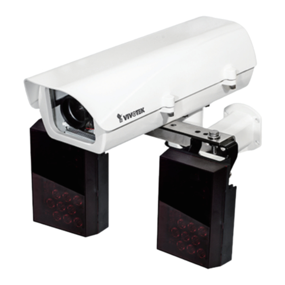
VIVOTEK Overview The VIVOTEK IP816A-LPC is a professional box network camera offering up to 60 fps @ 2-Megapixel resolution with superb image quality, even in the darkest hours of the night. Combined with IR lights and an outdoor housing, the solution is especially apt for traffic monitoring in challenging lighting conditions. -
Page 5: Read Before Use
VIVOTEK Read Before Use The use of surveillance devices may be prohibited by law in your country. The Network Camera is not only a high-performance web-ready camera but can also be part of a flexible surveillance system. It is the user’s responsibility to ensure that the operation of such devices is legal before installing this unit for its intended use. -
Page 6: Specifications
VIVOTEK Specifications Model Number IP816A-LPC enclosure Power Input 24VAC (+/-10%) Rating Current 3.5 A Heater Control 15°C (ON) / 25°C (OFF) Blower Control 35°C (ON) / 25°C (OFF) E n v i r o n m e n t a l O p e r a t i o n AE-237 Single heater: -20°C ~ +50°C... -
Page 7: Physical Description
VIVOTEK Physical Description Circulation Heater Heater for the dual-heater, Waterproof cable -40ºC model gland Power Supply Unit IMPORTANT: 1. Disconnect devices: A readily accessible disconnect device in the building installation wiring should be incorporated. 2. Electrical Connection: Only a qualified electrician is allowed to make electrical connections. -
Page 8: Installation
VIVOTEK Installation Loosen the socket screws using the included L-type hex key wrench, and open the cover. Secure the IR light units to the included iron brackets using a crescent wrench and a socket wrench. Secure both IR light units to the included iron bracket in the orientation shown below. - Page 9 VIVOTEK Secure the IR light bracket to the bottom of th enclosure. Secure one screw only at this stage of installation. Adjust the IR lights' shooting direction and tighten up the mount screws. You may need to adjust the shooting angles later.
- Page 10 VIVOTEK Pass the IR light units' signal wires through the waterproof connectors on the front. Loosen the retention hex screws of the enclosure. To access the screws, you can push the IR bracket to the side. 10 - User's Manual...
- Page 11 VIVOTEK User's Manual - 11...
- Page 12 VIVOTEK Check the inside of the enclosure to make sure the I/O wires can reach the power supply unit inside. An approximate of 25cm cable length is required. Install and tighten up the waterproof connectors. 12 - User's Manual...
- Page 13 VIVOTEK Prepare the AC24V power wires and a CAT5e Ethernet cable (user-supplied). Pass them through the waterproof connectors. You may need to remove the RJ45 connector, and use a crimping tool to connect the Ethernet wires to an RJ45 connector inside the enclosure. Use an Ethernet cable of the width of 5 ~ 6.5mm.
- Page 14 VIVOTEK When done, tighten up the waterproof connectors. Assemble the camera components, e.g., the CS ring and lens module. Align the buffer pad with the mounting hole at the bottom of the camera (the label side). Place the mounting plate on top of the buffer pad and then secure it to the camera. You may need adjust its position so that the lens module can flush align with the tempered glass.
- Page 15 VIVOTEK Secure the camera to the enclosure by securing screws through the keyhole slots. User's Manual - 15...
- Page 16 VIVOTEK Attach the AC24V power wires and power inputs from the IR light units to the terminal connector. Connect the Brown and Orange (26AWG) wires from both IR units to the terminal. Since AC 24V is polarity free, Connect AC 24V from outer source, 24V inputs for IR (2 pairs), and 24V inputs for camera, all to the same terminal connector.
- Page 17 VIVOTEK Listed below is the color scheme for wires coming fom the IR light units. Description Color Gauge IR status DO- Orange (26AWG) IR status DO+ Brown (26AWG) LED ON/OFF mode DO- Black (26AWG) LED ON/OFF mode DO+ (26AWG) Input(V-): 24V AC/DC or 12V DC...
- Page 18 VIVOTEK Having the wiring done inside the enclosure, you can install the enclosure bracket to a preferred location at your installation site. Drill mounting holes and a cable routing hole (if preferred) on a wall. Install the bracket. Lift the whole enclosure up to the installation position, and pass the 24V power wire and the Ethernet cables through the bracket.
- Page 19 VIVOTEK Mount the enclosure on to the installed bracket, and secure the connection by tightening the 4 socket screws. Due to the weight of the enclosure (5.5kg), it is best to have two men mounting the enclosure. Adjust zoom and focus and open a web session with the camera to tune for the best image.
- Page 20 VIVOTEK Close the top cover of the enclosure, tighten the screws,and secure another screw to the IR bracket. 20 - User's Manual...
- Page 21 VIVOTEK Firmware configurable options: Open a web console with the camera. Make sure that external IR is turned on in the night mode, and that the IR cut filter option is synchronized with the digital input you connected (default is DI1).
- Page 22 VIVOTEK In the Configuration > Media > Image settings page, select an application scenario, LPC street or LPC parking lot. Related parameters, such as shutter time, will be automatically changed for the scenario. If preferred, e.g., shooting fast moving vehicles, select the 60fps frame rate.
- Page 23 VIVOTEK In the night mode, check if the input signals are correctly detected. You may simulate the night mode by blocking the IR unit's light sensor. Change the triggering parameters when necessary. If your target area is a stretched out field of view, such as shooting a part of a highway, finding the best focus can be a problem.
- Page 24 VIVOTEK Operation Procedure: 1. Press the Snapshot Recording button, e.g., when a car is passing the field of view. A short, 2.5 seconds of video recording will be available (including 1 second of pre-recording and another second of post-recording). 2. The recording takes place on Stream 1 with a focusing result calculated from the full of the current field of view.
- Page 25 VIVOTEK General I/O Terminal Block This Network Camera provides a general I/O terminal block which is used to connect external input / output devices. The pin definitions are described below. The “AC/DC pw” pins can be used to connect both 24V AC and 12V DC power source.
- Page 26 VIVOTEK Switch Source BJT transistor Relay External device 26 - User's Manual...
- Page 27 VIVOTEK Hardware Reset Recessed Reset Button The reset button is used to reset the system or restore the factory default settings. Sometimes resetting the system can return the camera to normal operation. If the system problems remain after reset, restore the factory settings and install again.
-
Page 28: Installing To A Camera Stand
VIVOTEK Installing to a Camera Stand 1. Install the camera stand by drilling holes on the ceiling. 2. Secure the stand to ceiling using the screws and anchors. 3. Secure the camera to stand and tighten the fastening ring. 28 - User's Manual... -
Page 29: Network Deployment
VIVOTEK Network Deployment General Connection (with PoE) 4. If you have external devices such as sensors and alarms, connect them to the general I/O terminal block. Install the camera base to the mounting hole at the bottom of the camera. - Page 30 VIVOTEK Internet connection via a router Before setting up the Network Camera over the Internet, make sure you have a router and follow the steps below. 1. Connect your Network Camera behind a router, the Internet environment is illustrated below.
- Page 31 For more information with network configuration options (such as that of streaming ports), please refer to Configuration > Network Settings. VIVOTEK also provides the automatic port forwarding feature as an NAT traversal function with the precondition that your router must support the UPnP port forwarding feature.
-
Page 32: Software Installation
After your network environment is analyzed, please click Next to continue the program. 3. The program will search for all VIVOTEK network devices on the same LAN. 4. After a brief search, the installer window will prompt. Click on the MAC and model name that matches the one printed on the product label. -
Page 33: Ready To Use
VIVOTEK Ready to Use 1. A browser session with the Network Camera should prompt as shown below. 2. You should be able to see live video from your camera. You may also install the 32-channel recording software from the software CD in a deployment consisting of multiple cameras. For its installation details, please refer to its related documents. - Page 34 VIVOTEK 5. You may also use the Focus assist button or the auto focus function for the best imaging result. See Configuration > Image > Focus. Focus window 34 - User's Manual...
- Page 35 VIVOTEK NOTE: If using a CS-mount lens, please notice the specifications as below. The screw mount (distance A-C) must be shorter than 5.2mm; in case that the bottom of screw mount may hit the IR Cut Filter. User's Manual - 35...
-
Page 36: Accessing The Network Camera
3. The live video will be displayed in your web browser. 4. If it is the first time installing the VIVOTEK network camera, an information bar will prompt as shown below. Follow the instructions to install the required plug-in on your computer. - Page 37 VIVOTEK ► By default, the Network Camera is not password-protected. To prevent unauthorized access, it is highly recommended to set a password for the Network Camera. For more information about how to enable password protection, please refer to Security on page 103.
- Page 38 VIVOTEK IMPORTANT: 1. Currently the Network Camera utilizes a 32-bit ActiveX plugin. You CAN NOT open a management/view session with the camera using a 64-bit IE browser. 2. If you encounter this problem, try execute the Iexplore.exe program from C:\Windows\ SysWOW64.
-
Page 39: Using Rtsp Players
VIVOTEK Using RTSP Players To view the video streaming media using RTSP players, you can use one of the following players that support RTSP streaming. Quick Time Player VLC media player VLC media player 1. Launch the RTSP player. mpegable Player 2. -
Page 40: Using 3Gpp-Compatible Mobile Devices
VIVOTEK Using 3GPP-compatible Mobile Devices To view the streaming media through 3GPP-compatible mobile devices, make sure the Network Camera can be accessed over the Internet. For more information on how to set up the Network Camera over the Internet, please refer to Setup the Network Camera over the Internet on page To utilize this feature, please check the following settings on your Network Camera: 1. -
Page 41: Using Vivotek Recording Software
Network Camera to the Channel list. For detailed information about how to use the recording software, please refer to the user’s manual of the software or download it from http://www.vivotek.com. User's Manual - 41... -
Page 42: Main Page
VIVOTEK Main Page This chapter explains the layout of the main page. It is composed of the following sections: VIVOTEK INC. Logo, Host Name, Camera Control Area, Configuration Area, Menu, and Live Video Window. Resize Buttons VIVOTEK INC. Host Name... - Page 43 VIVOTEK Global View: Click on this item to display the Global View window. The Global View window contains a full view image (the largest frame size of the captured video) and a floating frame (the viewing region of the current video stream). The floating frame allows users to control the e-PTZ function (Electronic Pan/Tilt/Zoom).
- Page 44 VIVOTEK Configuration Area Client Settings: Click this button to access the client setting page. For more information, please refer to Client Settings on page 48. Configuration: Click this button to access the configuration page of the Network Camera. It is suggested that a password be applied to the Network Camera so that only the administrator can configure the Network Camera.
- Page 45 VIVOTEK PTZ Panel: This Network Camera supports “digital“ (e-PTZ) pan/tilt/zoom control, which allows roaming a smaller view frame within a large view frame. Please refer to PTZ settiings on page 116 for detailed information. Global View: Click on this item to display the Global View window. The Global View window contains a full view image (the largest frame size of the captured video) and a floating frame (the viewing region of the current video stream).
- Page 46 VIVOTEK Video and Audio Control Buttons: Depending on the Network Camera model and Network Camera configuration, some buttons may not be available. Snapshot: Click this button to capture and save still images. The captured images will be displayed in a pop-up window. Right-click the image and choose Save Picture As to save it in JPEG (*.jpg) or BMP (*.bmp) format.
- Page 47 VIVOTEK ■ The following window is displayed when the video mode is set to MJPEG: Video Title Time 2015/01/25 17:08:56 Video (HTTP-V) Title and Time Video 17:08:56 2015/01/25 Video Control Buttons Video Title: The video title can be configured. For more information, please refer to Media > Image on page 70.
-
Page 48: Client Settings
VIVOTEK Client Settings This chapter explains how to select the stream transmission mode and saving options on the local computer. When completed with the settings on this page, click Save on the page bottom to enable the settings. H.264 Media Options H.264 Media Options... - Page 49 VIVOTEK Two way audio Half duplex: Audio is transmitted from one direction at a time, e.g., from a PC holding a web console with the camera. Full duplex: Audio is transmitted in both directions simultaneously. MP4 Saving Options Users can record live video as they are watching it by clicking Start MP4 Recording on the main page.
- Page 50 VIVOTEK Joystick Settings Enable Joystick Connect to the USB plug of the joystick to a USB port on your management computer. Supported by the plug-in in the main page (Microsoft’s DirectX), once the plug-in in the main page is loaded, it will automatically detect if there is any joystick on the computer.
- Page 51 VIVOTEK Buttons Configuration In Button Configuration window, the left column shows the actions you can assign, and the right column shows the functional buttons and assigned actions. The number of buttons may differ from different joysticks. Please follow the steps below to configure your joystick buttons: 1.
- Page 52 VIVOTEK 3. The Assigned Action will appear beside Button 1 in the right column as shown in the following diagram. Note that a button can only be assigned with an action. If you want to modify the settings, select the action on the list and click Clear Selected.
- Page 53 VIVOTEK 5. Click OK to save the settings or click Cancel to discard the settings. NOTE: • If you want to assign Preset actions to your joystick, the preset locations should be configured in advance. • If your joystick is not working properly, it may need to be calibrated. Click the Calibrate button to open the Game Controllers window located in Microsoft Windows control panel and follow the instructions for trouble shooting.
-
Page 54: Configuration
Click Configuration on the main page to enter the camera setting pages. Note that only Administrators can access the configuration page. VIVOTEK offers an easy-to-use user interface that helps you set up your network camera with minimal effort. In order to simplify the user interface, the detailed information will be hidden unless you click on the function item. -
Page 55: System > General Settings
VIVOTEK System > General settings This section explains how to configure the basic settings for the Network Camera, such as the host name and system time. It is composed of the following two columns: System, and System Time. When finished with the settings on this page, click Save at the bottom of the page to enable the settings. - Page 56 VIVOTEK System time Keep current date and time: Select this option to preserve the current date and time of the Network Camera. The Network Camera’s internal real-time clock maintains the date and time even when the power of the system is turned off.
-
Page 57: System > Homepage Layout
Theme Options (the second tab on this page). The settings will be displayed automatically in this Preview field. The following shows the homepage using the default settings: ■ Hide Powered by VIVOTEK: If you check this item, it will be removed from the homepage. Logo graph Here you can change the logo that is placed at the top of your homepage. - Page 58 VIVOTEK Theme Options Here you can change the color of your homepage layout. There are three types of preset patterns for you to choose from. The new layout will simultaneously appear in the Preview field. Click Save to enable the settings.
- Page 59 VIVOTEK ■ Follow the steps below to set up the customed homepage: 1. Click Custom on the left column. 2. Click the field where you want to change the color on the right column. Color Selector Custom Pattern 3. The palette window will pop up as shown below.
-
Page 60: System > Logs
VIVOTEK System > Logs This section explains how to configure the Network Camera to send the system log to a remote server as backup. Log server settings Follow the steps below to set up the remote log: 1. Select Enable remote log. - Page 61 You can install the included ST7501 recording software, which provides an Event Management function group for delivering event messages via emails, GSM short messages, onscreen event panel, or to trigger an alarm, etc. For more information, refer to the ST7501 User Manual. VIVOTEK Network Cameras Internet 3G Cell phone HTTP...
-
Page 62: System > Parameters
VIVOTEK Access log Access log displays the access time and IP address of all viewers (including operators and administrators) in a chronological order. The access log is stored in the Network Camera’s buffer area and will be overwritten when reaching a certain limit. -
Page 63: System > Maintenance
Note: Do not power off the Network Camera during the upgrade! Follow the steps below to upgrade the firmware: 1. Download the latest firmware file from the VIVOTEK website. The file is in .pkg file format. 2. Click Browse… and locate the firmware file. - Page 64 VIVOTEK General settings > Restore This feature allows you to restore the Network Camera to factory default settings. Network: Select this option to retain the Network Type settings (please refer to Network Type on page 86). Daylight Saving Time: Select this option to retain the Daylight Saving Time settings (please refer to Import/Export files below on this page).
- Page 65 VIVOTEK ® 3. Open the file with Microsoft Notepad and locate your time zone; set the start and end time of DST. When completed, save the file. In the example below, DST begins each year at 2:00 a.m. on the second Sunday in March and ends at 2:00 a.m.
- Page 66 VIVOTEK The following message is displayed when attempting to upload an incorrect file format. Export language file: Click to export language strings. VIVOTEK provides nine languages: English, Deutsch, Español, Français, Italiano, 日本語, Português, 簡体中文, and 繁體中文 . Update custom language file: Click Browse… and specify your own custom language file to upload.
-
Page 67: Media > Image
VIVOTEK Media > Image This section explains how to configure the image settings of the Network Camera. It is composed of the following four columns: General settings, Picture settings, Exposure, and Privacy mask. General settings Video title Show_timestamp_and video_title_in_video_and_snapshots: Enter a name that will be displayed on the title bar of the live video as the picture shown below. - Page 68 VIVOTEK you select the Video Rotation mode in Media > Video window. See page 79 for more information. Rotate - Normal Flip Mirror Rotate 90° clockwise The rotation mode is disabled with the LPC application. The rotation here indicates clockwise rotation.
- Page 69 The Network Camera automatically removes the IR cut filter when a Digital Input is triggerred. For example, the digital input can come from a housing that is equipped with IR illumination and control circuits such as VIVOTEK’s AM-214 outdoor housing. ■ Schedule mode The Network Camera switches between day mode and night mode based on a specified schedule.
- Page 70 VIVOTEK Image settings On this page, you can tune the White balance, Image adjustment and WDR enhanced . Sensor Setting 1: For normal situations Sensor Setting 2: For special situations White balance: Adjust the value for the best color temperature.
- Page 71 By default, the LPC street mode is selected. If you need to enable the camera for the parking lot mode, please contact VIVOTEK’s technical support. When the street mode is enabled, WDR Pro will be disabled. The Exposure measurement window will be the full field of view, and the Exposure mode selection will be in the manual mode.
- Page 72 VIVOTEK Exposure On this page, you can set the Exposure level and Exposure mode. Detailed configurations will be automatically adjusted since the sensor library will automatically adjust the value according to the ambient light. When LPC application is enabled, the measurement window is forced to be full. The WDR Pro option is also disabled.
- Page 73 VIVOTEK Exposure control: ■ Exposure level: You can manually set the Exposure level, which ranges from -2.0 to +2.0 (dark to bright). You can click on the Exposure time and Gain control slide bars to specify a range of shutter time and Gain control values within which the camera can automatically tune to an optimal imaging result.
- Page 74 VIVOTEK ■ Exposure Profile: A pre-configured exposure profile is available with the LPC mode. This profile is set for the night mode operation and should be appropriate for most LPC applications. 74 - User's Manual...
- Page 75 If you apply a different lens to the camera, you can upload a different configuration file (containing an image library) for the specific lens module without updating the entire firmware. Please contact VIVOTEK's technical support for the supported Lens configuration files. Note that applying a new lens configuration requires a camera reboot.
- Page 76 VIVOTEK Focus Focus here refers to the Remote Back Focus, is applicable to Network Cameras that are equipped with stepping motor lens. The automated focus adjustment function eliminates the needs to physically adjust camera focus. In an outdoor deployment consisting of a large number of cameras, the auto focus function can be very helpful when these cameras become out of focus after days or weeks of operation.
- Page 77 VIVOTEK 6. Wait for the scan to complete. After a short while, the clearest image obtained should be displayed and the optimal focus range achieved. Use the arrow marks on the sides to fine-tune the focus if you are not satisfied with the results.
- Page 78 VIVOTEK Privacy mask Click Privacy Mask to open the settings page. On this page, you can block out sensitive zones to address privacy concerns. ■ To set the privacy mask windows, follow the steps below: 1. Click New to add a new window.
-
Page 79: Media > Video
VIVOTEK Media > Video Mode Due to system resources limitations, you can select one of the streaming modes for your application. Note that changes made to the video mode may require a system reboot and may erase the current Motion, Privacy mask, Exposure and Focus settings. - Page 80 VIVOTEK Stream settings This Network Camera supports multiple streams with frame sizes ranging from 176 x 144 to 1920 x 1080 pixels. The definition of multiple streams: ■ Stream 1: Users can define the frame size video quality and frame rate of up to 30/60fps.
- Page 81 VIVOTEK Click the stream item to display the detailed information. The maximum frame size will follow your settings in the above Viewing Window sections. This Network Camera provides real-time H.264 and MJPEG compression standards (Dual Codec) for real-time viewing. If the H.264...
- Page 82 VIVOTEK ■ Intra frame period Determine how often for firmware to plant an I frame. The shorter the duration, the more likely you will get better video quality, but at the cost of higher network bandwidth consumption. Select the intra frame period from the following durations: 1/4 second, 1/2 second, 1 second, 2 seconds, 3 seconds, and 4 seconds.
- Page 83 VIVOTEK If the JPEG mode is selected, the Network Camera sends consecutive JPEG images to the client, producing a moving effect similar to a filmstrip. Every single JPEG image transmitted guarantees the same image quality, which in turn comes at the expense of variable bandwidth usage. Because the media contents are a combination of JPEG images, no audio data is transmitted to the client.
-
Page 84: Media > Audio
VIVOTEK Media > Audio Audio Settings Mute: Select this option to disable audio transmission from the Network Camera to all clients. Note that if muted, no audio data will be transmitted even if audio transmission is enabled on the Client Settings page. -
Page 85: Network > General Settings
Use fixed IP address: Select this option to manually assign a static IP address to the Network Camera. 1. You can make use of VIVOTEK Installation Wizard 2 on the software CD to easily set up the Network Camera on LAN. Please refer to Software Installation on page 32 for details. - Page 86 VIVOTEK Primary DNS: The primary domain name server that translates host names into IP addresses. Secondary DNS: Secondary domain name server that backups the Primary DNS. Primary WINS server: The primary WINS server that maintains the database of computer names and IP addresses.
- Page 87 VIVOTEK NOTE: ► If the default ports are already used by other devices connected to the same router, the Network Camera will select other ports for the Network Camera. ► If UPnP is not supported by your router, you will see the following message: Error: Router does not support UPnP port forwarding.
- Page 88 VIVOTEK 4. In the Networking Services dialog box, select Universal Plug and Play and click OK. 5. Click Next in the following window. 6. Click Finish. UPnP is enabled. ► How does UPnP work? UPnP networking technology provides automatic IP configuration and dynamic discovery of devices added to a network.
- Page 89 VIVOTEK Enable IPv6 Select this option and click Save to enable IPv6 settings. Please note that this only works if your network environment and hardware equipment support ® IPv6. The browser should be Microsoft Internet Explorer 6.5, Mozilla Firefox 3.0 or above.
- Page 90 VIVOTEK Please follow the steps below to link to an IPv6 address: 1. Open your web browser. 2. Enter the link-global or link-local IPv6 address in the address bar of your web browser. 3. The format should be: http://[2001:0c08:2500:0002:0202:d1ff:fe04:65f4]/ IPv6 address 4.
- Page 91 VIVOTEK Port HTTPS port: By default, the HTTPS port is set to 443. It can also be assigned to another port number between 1025 and 65535. Two way audio port: By default, the two way audio port is set to 5060. Also, it can also be assigned to another port number between 1025 and 65535.
- Page 92 To stop talking, click again. FTP port: The FTP server allows the user to save recorded video clips. You can utilize VIVOTEK's Installation Wizard 2 to upgrade the firmware via FTP server. By default, the FTP port is set to 21.
-
Page 93: Network > Streaming Protocols
VIVOTEK Network > Streaming protocols HTTP streaming To utilize HTTP authentication, make sure that your have set a password for the Network Camera first; please refer to Security > User account on page 103 for details. Authentication: Depending on your network security requirements, the Network Camera provides two types of security settings for an HTTP transaction: basic and digest. - Page 94 VIVOTEK URL command -- http://<ip address>:<http port>/<access name for stream 1 or 2> For example, when the Access name for stream 2 is set to video2.mjpg: 1. Launch Mozilla Firefox. 2. Type the above URL command in the address bar. Press Enter.
- Page 95 VIVOTEK Authentication: Depending on your network security requirements, the Network Camera provides three types of security settings for streaming via RTSP protocol: disable, basic, and digest. basic authentication is selected, the password is sent in plain text format, but there can be potential risks of it being intercepted.
- Page 96 VIVOTEK Multicast settings for stream 1, 2: Click the items to display the detailed configuration information. Select the Always multicast option to enable multicast for stream 1 or 2. Unicast video transmission delivers a stream through point-to-point transmission; multicast, on the other hand, sends a stream to the multicast group address and allows multiple clients to acquire the stream at the same time by requesting a copy from the multicast group address.
- Page 97 IP address, to have a fixed host and domain name. Express link Express Link is a free service provided by VIVOTEK server, which allows users to register a domain name for a network device. One URL can only be mapped to one MAC address.
- Page 98 DDNS: Dynamic domain name service Enable DDNS: Select this option to enable the DDNS setting. Provider: Select a DDNS provider from the provider drop-down list. VIVOTEK offers Safe100.net, a free dynamic domain name service, to VIVOTEK customers. It is recommended that you register Safe100.net to access VIVOTEK’s Network Cameras from the...
- Page 99 4. Select Enable DDNS and click Save to enable the setting. ■ CustomSafe100 VIVOTEK offers documents to establish a CustomSafe100 DDNS server for distributors and system integrators. You can use CustomSafe100 to register a dynamic domain name if your distributor or system integrators offer such services.
- Page 100 VIVOTEK Network > QoS (Quality of Service) Quality of Service refers to a resource reservation control mechanism, which guarantees a certain quality to different services on the network. Quality of service guarantees are important if the network capacity is insufficient, especially for real-time streaming multimedia applications. Quality can be defined as, for instance, a maintained level of bit rate, low latency, no packet dropping, etc.
- Page 101 VIVOTEK QoS/DSCP (the DiffServ model) DSCP-ECN defines QoS at Layer 3 (Network Layer). The Differentiated Services (DiffServ) model is based on packet marking and router queuing disciplines. The marking is done by adding a field to the IP header, called the DSCP (Differentiated Services Codepoint). This is a 6-bit field that provides 64 different class IDs.
-
Page 102: Network > Snmp (Simple Network Management Protocol)
VIVOTEK Network > SNMP (Simple Network Management Protocol) This section explains how to use the SNMP on the network camera. The Simple Network Management Protocol is an application layer protocol that facilitates the exchange of management information between network devices. It helps network administrators to remotely manage network devices and find, solve network problems with ease. -
Page 103: Security > User Accounts
VIVOTEK Security > User accounts This section explains how to enable password protection and create multiple accounts. Root Password The administrator account name is “root”, which is permanent and can not be deleted. If you want to add more accounts in the Manage User column, please apply the password for the “root”... -
Page 104: Security > Https (Hypertext Transfer Protocol Over Ssl)
VIVOTEK Security > HTTPS (Hypertext Transfer Protocol over SSL) This section explains how to enable authentication and encrypted communication over SSL (Secure Socket Layer). It helps protect streaming data transmission over the Internet on higher security level. Create and Install Certificate Method Before using HTTPS for communication with the Network Camera, a Certificate must be created first. - Page 105 VIVOTEK 5. Click Save to preserve your configuration, and your current session with the camera will change to the encrypted connection. 6. If your web session does not automatically change to an encrypted HTTPS session, click Home to return to the main page. Change the URL address from “http://” to “https://“ in the address bar and press Enter on your keyboard.
- Page 106 VIVOTEK Create certificate request and install 1. Select the option from the Method pull-down menu. 2. Click Create certificate to proceed. 3. The following information will show up in a pop-up window after clicking Create. Then click Save to generate the certificate request.
- Page 107 VIVOTEK 5. Look for a trusted certificate authority, such as Symantec’s VeriSign Authentication Services, that issues digital certificates. Sign in and purchase the SSL certification service. Copy the certificate request from your request prompt and paste it in the CA’s signing request window. Proceed with the rest of the process as CA’s instructions on their webpage.
- Page 108 VIVOTEK 7. Open a new edit, paste the certificate contents, and press ENTER at the end of the contents to add an empty line. 8. Convert file format from DOS to UNIX. Open File menu > Conversions > DOS to Unix.
- Page 109 VIVOTEK 9. Save the edit using the “.crt” extension, using a file name like “CAcert.crt.” 10. Return to the original firmware session, use the Browse button to locate the crt certificate file, and click Upload to enable the certification. User's Manual - 109...
- Page 110 VIVOTEK Note that a 11. When the certifice file is successfully loaded, its status will be stated as Active. certificate must have been created and installed before you can click on the “Save" button for the configuration to take effect.
-
Page 111: Security > Access List
VIVOTEK Security > Access List This section explains how to control access permission by verifying the client PC’s IP address. General Settings Maximum number of concurrent streaming connection(s) limited to: Simultaneous live viewing for 1~10 clients (including all video streams). The default value is 10. If you modify the value and click Save, all current connections will be disconnected and automatically attempt to re-link (IE Explorer or Quick Time Player). - Page 112 VIVOTEK ■ Refresh: Click this button to refresh all current connections. ■ Add to deny list: You can select entries from the Connection Status list and add them to the Deny List to deny access. Please note that those checked connections will only be disconnected temporarily and will automatically try to re-link again (IE Explore or Quick Time Player).
- Page 113 VIVOTEK There are three types of rules: Single: This rule allows the user to add an IP address to the Allowed/Denied list. For example: 192.168.2.1 Network: This rule allows the user to assign a network address and corresponding subnet mask to the Allow/Deny List.
- Page 114 3. Authentication server (usually a RADIUS server): Checks the client certificate and decides whether to accept the end user’s access request. ■ VIVOTEK Network Cameras support two types of EAP methods to perform authentication: EAP- PEAP and EAP-TLS. Please follow the steps below to enable 802.1x settings: 1.
- Page 115 VIVOTEK 3. When all settings are complete, move the Network Camera to the protected LAN by connecting it to an 802.1x enabled switch. The devices will then start the authentication automatically. NOTE: ► The authentication process for 802.1x: 1. The Certificate Authority (CA) provides the required signed certificates to the Network Camera (the supplicant) and the RADIUS Server (the authentication server).
-
Page 116: Ptz > Ptz Settings
VIVOTEK PTZ > PTZ settings This section explains how to control the Network Camera’s Pan/Tilt/Zoom operation. There are two ways to enable the camera control function: 1. Digital: Control the e-PTZ operation. Within a field of view, it allows users to quickly move the focus to a target area for close-up viewing without physically moving the camera. - Page 117 VIVOTEK When completed with the e-PTZ settings, click Save to enable the settings on this page. Home page in the E-PTZ Mode 2012/04/10 17:08:56 x3.3 ■ The e-Preset Positions will also be displayed on the home page. Select one from the drop-down list, and the Network Camera will move to the selected position.
- Page 118 VIVOTEK Patrol settings You can select some preset positions for the Network Camera to patrol. Please follow the steps below to set up a patrol schedule: 1. Select the preset locations on the list, and click 2. The selected preset locations will be displayed on the Patrol locations list.
-
Page 119: Ptz
Then you can configure the PTZ driver and RS485 port with the following settings. VIVOTEK provides the following PTZ drivers: DynaDome/SmartDOME, Lilin PIH-7x00, Pelco D, and Pelco P protocol. If none of the above PTZ drivers is supported by your PTZ scanner, please select Custom camera (scanner). - Page 120 VIVOTEK Transparent HTTP Tunnel: If you want to use your own RS-485 device, you can use UART commands to build a Transparent HTTP Tunnel. The UART commands will be sent through HTTP tunnel established between the RS-485 device and the camera. For detailed application notes, http://www.vivotek.com/downloadfiles/support/...
- Page 121 VIVOTEK Home page in Mechanical PTZ Mode The Preset Positions will also be displayed on the home page. Select one from the drop-down list, and the Network Camera will move to the selected preset position. User's Manual - 121...
- Page 122 VIVOTEK Patrol Settings You can select some preset positions for the Network Camera to patrol through them. Please follow the steps below to set up a patrol schedule: 1. Select preset locations on the list and click on the >> button. They will be replicated to the Patrol Locations.
- Page 123 VIVOTEK Custom Command If Custom Camera (scanner) is selected as the PTZ driver, you will need to configure command buttons to control the PTZ scanner. Click Custom Command to open the Custom Command page to set the commands in the Control Settings session. Please refer to your PTZ scanner's documentation to enter the commands in the following fields.
-
Page 124: Event > Event Settings
VIVOTEK Event > Event settings This section explains how to configure the Network Camera to responds to particular situations (event). A typical application is that when a motion is detected, the Network Camera sends buffered images to an FTP server or e-mail address as notifications. Click on Help, there is an illustration shown in the pop-up window explaining that an event can be triggered by many sources, such as motion detection or external digital input devices. - Page 125 VIVOTEK ■ Event name: Enter a name for the event setting. ■ Enable this event: Select this option to enable the event setting. ■ Priority: Select the relative importance of this event (High, Normal, or Low). Events with a higher priority setting will be executed first.
- Page 126 VIVOTEK ■ Audio detection A preset threshold can be configured with an external microphone as the trigger to system event. The triggering condition can be an input exceeding or falling below a threshold. Audio detection can take place as a complement to motion detection or as a method to detect activities not covered by the camera's view.
- Page 127 VIVOTEK 3. Action Define the actions to be performed by the Network Camera when a trigger is activated. ■ Trigger digital output for seconds Select this option to turn on the external digital output device when a trigger is activated. Specify the length of the trigger interval in the text box.
- Page 128 VIVOTEK Add server It is necessary to configure the server and media settings so that the Network Camera will know what action to take (such as which server to send the media files to) when a trigger is activated. Click server to open the server setting window.
- Page 129 VIVOTEK To verify if the email settings are correctly configured, click Test. The result will be shown in a pop-up window. If successful, you will also receive an email indicating the result. Click Save server to enable the settings. Note that after you set up the first event server, the new event server will automatically display on the Server list.
- Page 130 VIVOTEK ■ Passive mode Most firewalls do not accept new connections initiated from external requests. If the FTP server supports passive mode, select this option to enable passive mode FTP and allow data transmission to pass through the firewall. The firmware default has the Passive mode checkbox selected.
- Page 131 VIVOTEK Network storage: Select to send the media files to a network storage location when a trigger is activated. Please refer to NAS server on page 151 for details. Note that only one NAS server can be configured. Click Save server to enable the settings.
- Page 132 VIVOTEK Click 20150120 to open the directory: The format is: HH (24r) Click to open the file list for that hour 2015/01/20 2015/01/20 Click to go back to the previous Click to delete level of the directory selected items Click to delete all...
- Page 133 VIVOTEK Add media Add media Click to open the media setting window. You can specify the type of media that will be sent when a trigger is activated. A total of 5 media settings can be configured. There are three choices of media types available: Snapshot, Video Clip, and System log.
- Page 134 VIVOTEK ■ Add date and time suffix to the file name Select this option to add a date/time suffix to the file name. For example: Snapshot_20140513_100341 File name prefix Date and time suffix The format is: YYYYMMDD_HHMMSS Click Save media to enable the settings.
- Page 135 VIVOTEK ■ Maximum file size Specify the maximum file size allowed. Some users may need to stitch the video clips together. ■ File name prefix Enter the text that will be appended to the front of the file name. For example: Video_20150113_100341 File name prefix...
- Page 136 VIVOTEK In the Event settings column, the Servers and Medias you configured will be listed; please make sure the Event -> Status is indicated as ON, in order to enable the event triggering action. When completed, click the Save event button to enable the settings and click Close to exit Event Settings page.
- Page 137 Please note that there is a limited number of customized scripts you can upload; if the current amount of customized scripts has reached the limit, an alert message will prompt. If you need more information, please contact VIVOTEK technical support. Click to upload a file...
-
Page 138: Applications > Motion Detection
VIVOTEK Applications > Motion detection This section explains how to configure the Network Camera to enable motion detection. A total of three motion detection windows can be configured. 2015/1/20 14:39:12 Motion Detection Setting 1: For normal situations hallway Motion Detection Setting 2:... - Page 139 VIVOTEK A green bar indicates that even though motions have been detected, the event has not been triggered because the image variations still fall under the preset threshold. Percentage = 30% If you want to configure other motion detection settings for day/night/schedule mode, please click Profile to open the Motion Detection Profile Settings page as shown below.
- Page 140 VIVOTEK NOTE: ► How does motion detection work? There are two motion detection parameters: Sensitivity and Percentage. In the illustration above, frame A and frame B are two sequential images. Pixel differences between the two frames are detected and highlighted in gray (frame C) and will be compared with the sensitivity setting. Sensitivity is a value that expresses the sensitivity to moving objects.
-
Page 141: Applications > Di And Do
VIVOTEK Applications > DI and DO Connect DI or DO devices to the camera's terminal block, the camera will automatically detect the current connection state as pulled-high or pulled-low. You may then define the triggering condition. Digital input: Select High or Low as the state of the signal to define the "Normal status" for the digital input. -
Page 142: Applications > Audio Detection
VIVOTEK Applications > Audio detection Audio detection, along with video motion detection, is applicable in the following scenarios: 1. Detection of activities not covered by camera view, e.g., a loud input by gun shots or breaking a door/window. 2. A usually noisy environment, such as a factory, suddenly becomes quiet due to a breakdown of machines. - Page 143 VIVOTEK You can use the Profile window to configure a different Audio detection setting. For example, a place can be noisy in the day time and become very quiet in the night. 1. Click on the Enable this profile checkbox. Once the Audio detection window is opened, the current sound input will be interactively indicated by a fluctuating yellow wave diagram.
-
Page 144: Package Management (Vadp, Vivotek Application Development Platform)
Package management (VADP, VIVOTEK Application Development Platform) Users can store and execute VIVOTEK's or 3rd-party software modules onto the camera's flash memory or SD card. These software modules can apply in video analysis for intelligent video applications such as license plate recognition, object counting, or as an agent for edge recording, etc. - Page 145 VIVOTEK To start a module, select the checkcircle in front, and click the Start button. If you should need to remove a module, select the checkcircle in front and then click the Stop button. By then the module status will become OFF, and the X button will appear at the end of the row.
-
Page 146: Snapshot Focus
Limitations: 1. This package should be enabled or separately downloaded from VIVOTEK’s website or technical support to a camera. You may need to register yourself on VIVOTEK’s website and activate the package. 2. This feature does not support the MJPEG stream. If a camera’s stream 1 is configured into MJPEG, a warning message will prompt. - Page 147 VIVOTEK 2. The recording takes place on Stream 1 with a focusing result calculated from the full of the current field of view. 3. The Snapshot Focus comes with an embedded Quick time player. Users can review the current focusing results on a viewing window. Users can also use the left arrow key on their keyboard to go through the recording in a frame-by-frame manner (after the video is played once).
-
Page 148: Recording > Recording Settings
VIVOTEK Recording > Recording settings This section explains how to configure the recording settings for the Network Camera. Recording Settings Insert your SD card and click here to test NOTE: ► Please remember to format your SD card via the camera’s web console (in the Local storage . - Page 149 VIVOTEK If you enable adaptive recording and enable time-shift cache stream on Camera A, only when an event is triggered on Camera A will the server record the full frame rate streaming data; otherwise, it will only request the I frame data during normal monitoring, thus effectively saves bandwidth and storage space.
- Page 150 VIVOTEK 2. Destination You can select the SD card or network storage (NAS) for the recorded video files. If you have not configured a NAS server, see details in the following. NAS server Click Add NAS server to open the server setting window and follow the steps below to set up: 1.
- Page 151 VIVOTEK If successful, you will receive a test.txt file on the network storage server. 3. Enter a server name. 4. Click Save to complete the settings and click Close to exit the page. ■ Capacity: You can choose either the entire free space available or limit the reserved space. The recording size limit must be larger than the reserved amount for cyclic recording.
- Page 152 VIVOTEK Event f you want to enable recording notification, please click to configure event triggering settings. Please refer to Event > Event settings on page 124 for more details. When completed, select Enable this recording. Click Save to enable the setting and click Close to exit this page.
-
Page 153: Local Storage > Sd Card Management
VIVOTEK Local storage > SD card management This section explains how to manage the local storage on the Network Camera. Here you can view SD card status, and implement SD card control. SD card staus This column shows the status and reserved space of your SD card. Please remember to format the SD card when using for the first time. -
Page 154: Local Storage > Content Management
VIVOTEK Local storage > Content management This section explains how to manage the content of recorded videos on the Network Camera. Here you can search and view the records and view the searched results. Searching and Viewing the Records This column allows the user to set up search criteria for recorded data. If you do not select any criteria and click Search button, all recorded data will be listed in the Search Results column. - Page 155 VIVOTEK Search Results The following is an example of search results. There are four columns: Trigger time, Media type, Trigger type, and Locked. Click to sort the search results in either direction. Enter a key word to filter the Numbers of entries displayed...
- Page 156 VIVOTEK ■ Lock/Unlock: Select the desired search results, then click this button. The selected items will become Locked, which will not be deleted during cyclic recording. You can click again to unlock the selections. For example: Click to switch pages ■...
-
Page 157: Appendix
VIVOTEK Appendix URL Commands for the Network Camera 1. Overview For some customers who already have their own web site or web control application, the Network Camera/Video Server can be easily integrated through URL syntax. This section specifies the external HTTP-based application programming interface. - Page 158 VIVOTEK 3. General CGI URL Syntax and Parameters CGI parameters are written in lower-case and as one word without any underscores or other separators. When the CGI request includes internal camera parameters, these parameters must be written exactly as they are named in the camera or video server.
- Page 159 VIVOTEK 5. Get Server Parameter Values Note: The access right depends on the URL directory. Method: GET/POST Syntax: http://<servername>/cgi-bin/anonymous/getparam.cgi?[<parameter>] [&<parameter>…] http://<servername>/cgi-bin/viewer/getparam.cgi?[<parameter>] [&<parameter>…] http://<servername>/cgi-bin/operator/getparam.cgi?[<parameter>] [&<parameter>…] http://<servername>/cgi-bin/admin/getparam.cgi?[<parameter>] [&<parameter>…] Where the <parameter> should be <group>[_<name>] or <group>[.<name>]. If you do not specify any parameters, all the parameters on the server will be returned.
- Page 160 VIVOTEK Example: Request IP address and its response Request: http://192.168.0.123/cgi-bin/admin/getparam.cgi?network_ipaddress Response: HTTP/1.0 200 OK\r\n Content-Type: text/html\r\n Context-Length: 33\r\n \r\n network.ipaddress=192.168.0.123\r\n 160 - User's Manual...
- Page 161 (Note: The return page can be a general HTML file(.htm, .html) or a VIVOTEK server script executable (.vspx) file. It cannot be a CGI commandor have any extra parameters.This parameter must be placed at the end of the parameter list Return: HTTP/1.0 200 OK\r\n...
- Page 162 VIVOTEK where<parameter pair> is <parameter>=<value>\r\n [<parameter pair>] Only the parameters that you set and are readable will be returned. Example: Set the IP address of server to 192.168.0.123: Request: http://myserver/cgi-bin/admin/setparam.cgi?network_ipaddress=192.168.0.123 Response: HTTP/1.0 200 OK\r\n Content-Type: text/html\r\n Context-Length: 33\r\n \r\n network.ipaddress=192.168.0.123\r\n...
- Page 163 VIVOTEK 7. Available parameters on the server Valid values: VALID VALUES DESCRIPTION string[<n>] Text strings shorter than ‘n’ characters. The characters “,’,<,>,& are invalid. string[n~m] Text strings longer than `n’ characters and shorter than `m’ characters. The characters “,’,<,>,& are invalid.
- Page 164 VIVOTEK 7.1 system Group: system NAME VALUE DEFAULT SECURITY DESCRIPTION (get/set) hostname string[64] IP816A-HP, Host name of server IP816A-LP (Network Camera, C(Street), Wireless Network Camera, Video Server, IP816A-LP Wireless Video Server). C(Parkinglo * DEFAULT value depends on service ledoff <boolean>...
- Page 165 VIVOTEK -280: GMT-07:00 Mountain Time, Denver -281: GMT-07:00 Arizona -240: GMT-06:00 Central America, Central Time, Mexico City, Saskatchewan -200: GMT-05:00 Eastern Time, New York, Toronto -201: GMT-05:00 Bogota, Lima, Quito, Indiana -180: GMT-04:30 Caracas -160: GMT-04:00 Atlantic Time, Canada, La Paz, Santiago...
- Page 166 VIVOTEK Tbilisi, Yerevan 180: GMT 04:30 Kabul 200: GMT 05:00 Ekaterinburg, Islamabad, Karachi, Tashkent 220: GMT 05:30 Calcutta, Chennai, Mumbai, New Delhi 230: GMT 05:45 Kathmandu 240: GMT 06:00 Almaty, Novosibirsk, Astana, Dhaka, Sri Jayawardenepura 260: GMT 06:30 Rangoon 280: GMT 07:00 Bangkok, Hanoi,...
- Page 167 VIVOTEK -80,-40,0, 40,41,80, 81,82,83, 120,140, 380,400,48 updateinterval 0 to Disable automatic time 3600, adjustment, otherwise, it indicates 86400, the seconds between NTP automatic 604800, update intervals. 2592000 restore Restore the system parameters to <positive default values after <value> seconds. integer>...
- Page 168 VIVOTEK When cooperating with others, the system parameters will be restored to the default value except for a union of the combined results. restoreexceptvadp <integer> Restore the system parameters to default values except the vadp parameters and VADP modules that stored in the system.
- Page 169 VIVOTEK language_count <integer> Number of webpage languages available on the server. language_i<0~(count-1)> string[16] language_i0 Available language lists. : English language_i1 : Deutsch language_i2 : Español language_i3 : Français language_i4 : Italiano language_i5 : 日本語 language_i6 : Português language_i7 : 简体中文...
- Page 170 VIVOTEK onlinenum_httppush integer Current number of HTTP push server connections. eth_i0 <string> <product Get network information from dependent> mii-tool. vi_i<0~(nvi-1)> <boolean> Virtual input <product dependent> 0 => Inactive 1 => Active (capability.nvi > 0) 7.3 digital input behavior define Group: di_i<0~(ndi-1)>(capability.ndi >...
- Page 171 VIVOTEK 7.5 security Group: security NAME VALUE DEFAULT SECURITY DESCRIPTION (get/set) privilege_do view, operator, operator Indicate which privileges and admin above can control digital output (capability.ndo > 0) privilege_camctrl view, operator, view Indicate which privileges and admin above can control PTZ (capability.ptzenabled >...
- Page 172 VIVOTEK 7.6 network Group: network NAME VALUE DEFAULT SECURITY DESCRIPTION (get/set) preproces <positive <blank> An 32-bit integer, each bit can be set separately as integer> follows: Bit 0 => HTTP service; Bit 1=> HTTPS service; Bit 2=> FTP service; Bit 3 => Two way audio and RTSP Streaming service;...
- Page 173 VIVOTEK address> dns2 <ip <blank> Secondary DNS server. address> wins1 <ip <blank> Primary WINS server. address> wins2 <ip <blank> Secondary WINS server. address> 7.6.1 802.1x Subgroup of network: ieee8021x(capability.protocol.ieee8021x > 0) NAME VALUE DEFAULT SECURITY DESCRIPTION (get/set) enable <boolean> Enable/disable IEEE 802.1x...
- Page 174 VIVOTEK 7.6.2 QOS Subgroup of network: qos_cos (capability.protocol.qos.cos > 0) NAME VALUE DEFAULT SECURITY DESCRIPTION (get/set) enable <boolean> Enable/disable CoS (IEEE 802.1p) vlanid 1~4095 VLAN ID video Video channel for CoS audio Audio channel for CoS (capability.naudio > 0) eventalarm...
- Page 175 VIVOTEK 7.6.4 FTP Subgroup of network: ftp NAME VALUE DEFAULT SECURITY DESCRIPTION (get/set) port 21, 1025~65535 Local ftp server port. 7.6.5 HTTP Subgroup of network: http NAME VALUE DEFAULT SECURITY DESCRIPTION (get/set) port 80, 1025 ~ HTTP port. 65535 alternateport...
- Page 176 VIVOTEK 7.6.7 RTSP Subgroup of network: rtsp (capability.protocol.rtsp > 0) NAME VALUE DEFAULT SECURITY DESCRIPTION (get/set) port 554, 1025 ~ RTSP port. 65535 (capability.protocol.rtsp=1) anonymousviewing <boolean> Enable anoymous streaming viewing. authmode disable, basic RTSP authentication mode. basic, (capability.protocol.rtsp=1) digest s0_accessname string[32] live.sdp...
- Page 177 VIVOTEK (capability.naudio > 0) 1 ~ 255 Mutlicast time to live value. 7.6.8 SIP port Subgroup of network: sip (capability.protocol.sip> 0) NAME VALUE DEFAULT SECURITY DESCRIPTION (get/set) port 1025 ~ 65535 5060 SIP port. 7.6.9 RTP port Subgroup of network: rtp...
- Page 178 VIVOTEK connection(s). type 0, 1 Ipfilter policy : 0 => allow 1 => deny ipv4list_i<0~9> string[31] <blank> IPv4 address list. Single address: <ip address> Network address: <ip address / network mask> Range address:<start ip address - end ip address> ipv6list_i<0~9>...
- Page 179 VIVOTEK 1/7 (others) ptzstatus <integer> A 32-bit integer, each bit can be set separately as follows: Bit 0 => Support camera control function; 0(not support), 1(support) Bit 1 =>Built-in or external camera; 0 (external), 1(built-in) Bit 2 => Support pan operation;...
- Page 180 VIVOTEK 7.8.1Video input setting per channel Group:videoin_c<0~(n-1)> for n channel products, and m is stream number NAME VALUE DEFAULT SECURITY DESCRIPTION (get/set) cmosfreq 50, 60 CMOS frequency. (capability.videoin.type=2) mode 0,1,2 Set video mode 0: Dual stream mode (Max. 30fps) 1: Dual stream mode with video rotation (Max.
- Page 181 VIVOTEK product dependent. HP is outdoor. LPC(Parkinglot) is manual. LPC(Street) is manual. piris_position 1~100 Position of piris enableblc Enable backlight compensation maxgain 0~100 100/40 Manual set maximum gain value. Note: default value is product dependent. HP is 100. LPC(Parkinglot) is 40.
- Page 182 VIVOTEK settings. Preview settings of video profile. s<0~(m-1)>_codectype mjpeg, h264 H264 Video codec type. s<0~(m-1)>_resolution Reference s0:1920x1080 Video resolution in pixels. capability_vide s1:640x360 oin_resolution s<0~(m-1)>_h264_intraperi 250, 500, 1000 Intra frame period in 1000, 2000, milliseconds. 3000, 4000 s<0~(m-1)>_h264_ratecont cbr, vbr...
- Page 183 VIVOTEK 1: main profile 2: high profile s<0~(m-1)>_h264_priorityp framerate,imag s0:framerate Set prioritypolicy olicy equality s1:imagequality s<0~(m-1)>_mjpeg_ratecon cbr, vbr s0: vbr cbr, constant bitrate trolmode s1: vbr vbr, fix quality s<0~(m-1)>_mjpeg_quant 1~5, Quality of JPEG video. 99, 100 99 is the customized manual input setting.
- Page 184 VIVOTEK wdr_strength=0 level2: wdr_mode=1, wdr_strength=1 level3: wdr_mode=1, wdr_strength=2 Note: default wdr_modevalue is product dependent. HP is 1. LPC(Parkinglot) is 0. LPC(Street) is 0. 7.8.1.1 Alternative video input profiles per channel In addition to the primary setting of video input, there can be alternative profile video input setting for each channel which might be for different scene of light (daytime or nighttime).
- Page 185 VIVOTEK Note: default value is product dependent. HP is 6. LPC(Parkinglot) is 0. LPC(Street) is 0. maxgain 0~100 100/40 Manual set maximum gain value. Note: default value is product dependent. HP is 100. LPC(Parkinglot) is 40. LPC(Street) is 40. mingain 0~100 Manual set minimum gain value.
- Page 186 VIVOTEK LPC(Street) is 0. whitebalance auto, auto2, auto “auto& auto2” indicate auto white manual, balance. manual2, “auto2” indicates auto white rbgain <product balance“manual& manual2” indicate dependent> keep current value. 2 which is designed for non-bundle lens models “rbgain” indicates using rgain and gbain.
- Page 187 VIVOTEK LPC(Parkinglot) is manual. LPC(Street) is manual. piris_position 1~100 Position of piris wdr_mode 30fps:WDRPro 60fps:no WDR wdr_strength WDRPro:3 level (from low to high) level1: wdr_mode=1, wdr_strength=0 level2: wdr_mode=1, wdr_strength=1 level3: wdr_mode=1, wdr_strength=2 Note: default wdr_mode value is product dependent. HP is 1.
- Page 188 VIVOTEK 7.10 IR cut control Group: ircutcontrol(capability.nvideoinprofile> 0) NAME VALUE DEFAULT SECURITY DESCRIPTION (get/set) mode auto, auto/di0 Set IR cut control mode day, Note: default value is product night, dependent. di0, HP is auto. di1, LPC(Parkinglot) is di0. di2, LPC(Street) is di0.
- Page 189 VIVOTEK saturationpercent 0~100 Adjust saturation value of percentage when saturation=100 contrastpercent 0~100 Adjust contrastpercent of image sharpnesspercent 0~100 Adjust sharpnessvalue of percentage when sharpness=100 gammacurve 0~100 Gamma curve. lowlightmode <boolean> Enable/disable low light mode. dnr_mode 0:disable 1:enable Note: default dnrmode value is product dependent.
- Page 190 VIVOTEK profile_i0_policy day, night The mode which the profile is applied to. night, schedule profile_i0_begintime hh:mm 18:00 Begin time of schedule mode. profile_i0_endtime hh:mm 06:00 End time of schedule mode. profile_i0_brightness -5~5,100 Adjust brightness of image according to mode settings.
- Page 191 VIVOTEK upport" is 1 profile_i0_scene_mode lpcstreet lpcstreet Value of scene mode lpcparkinglot * DEFAULT is according to lpcparkin "system_info_extendedmodelname" glot If it is "IP816A-LPC(Street)", DEFAULT is lpcstreet. If it is "IP816A-LPC(Parking)", DEFAULT is lpcparkinglot. * Only available when "capability_image_c<n>_scenemode_s upport" is 1...
- Page 192 VIVOTEK 7.12 Image setting for preview Group: imagepreview_c<0~(n-1)> for n channel products NAME VALUE DEFAULT SECURITY DESCRIPTION (get/set) brightness -5~5,100 Adjust brightness of image according to mode settings. saturation -5~5,100 Adjust saturation of image according to mode settings. 100 for saturation percentage mode.
- Page 193 VIVOTEK lpcparkinglot * DEFAULT is according to lpcparkinglot "system_info_extendedmodelname" If it is "IP816A-LPC(Street)", DEFAULT is lpcstreet. If it is "IP816A-LPC(Parking)", DEFAULT is lpcparkinglot. * Only available when "capability_image_c<n>_scenemode_support" is 1 Group: imagepreview NAME VALUE DEFAULT SECURITY DESCRIPTION (get/set) videoin_whitebalance auto,...
- Page 194 VIVOTEK 7.13 Exposure window setting per channel Group: exposurewin_c<0~(n-1)> for n channel products NAME VALUE DEFAULT SECURITY DESCRIPTION (get/set) mode auto, custom,blc auto The mode indicates how to decide the exposure. auto: Use full view as the only one exposure window.
- Page 195 VIVOTEK 7.14 Audio input per channel Group: audioin_c<0~(n-1)> for n channel products (capability.audioin>0) NAME VALUE DEFAULT SECURITY DESCRIPTION (get/set) source linein linein micin => use built-in microphone input. linein => use external microphone input. mute 0, 1 Disable audio mute.
- Page 196 VIVOTEK schedule profile_i0_begintime hh:mm 18:00 Begin time of schedule mode. profile_i0_endtime hh:mm 06:00 End time of schedule mode. profile_i0_alarm_level 1~100 Audio detection alarm level 7.15 Time Shift settings Group: timeshift, c for n channel products, m is stream number(capability.timeshift > 0)
- Page 197 VIVOTEK ~ (m-1). i<0~(m-1)>_policy day, night The mode which night, the profile is schedule applied to. i<0~(m-1)>_begintime hh:mm 18:00 Begin time of schedule mode. i<0~(m-1)>_endtime hh:mm 06:00 End time of schedule mode. i<0~(m-1)>_win_i<0~2>_enable <boolean> Enable motion window. i<0~(m-1)>_win_i<0~2>_name string[14] <blank>...
- Page 198 VIVOTEK 7.17 Tempering detection settings Group: tampering_c<0~(n-1)>for n channel product (capability.tampering > 0) NAME VALUE DEFAULT SECURITY DESCRIPTION (get/set) enable <boolean> Enable or disable tamper detection. threshold 0 ~ 255 Threshold of tamper detection. duration 10 ~ 20 If tampering value exceeds the ‘threshold’ for more than ‘duration’...
- Page 199 VIVOTEK 7.19 Express link Group:expresslink PARAMETER VALUE Default SECURITY DESCRIPTION (get/set) enable <boolean> Enable or disable express link. state onlycheck, badnetwork Camera will check the status of network onlyoffline, environment and express link URL checkonline, badnetwork string[64] NULL The url user define to link to camera 7.20 UPnP presentation...
- Page 200 VIVOTEK 7.22 System log Group: syslog NAME VALUE DEFAULT SECURITY DESCRIPTION (get/set) enableremotelog <boolean> Enable remote log. serverip <IP address> <blank> Log server IP address. serverport 514, Server port used for log. 1025~65535 level Levels used to distinguish the importance of the information:...
- Page 201 VIVOTEK 7.23 camera PTZ control Group: camctrl(capability.camctrl.httptunnel> 0) NAME VALUE DEFAULT SECURITY DESCRIPTION (get/set) enableptztunnel <boolean> Enable HTTP tunnel for camera control. Group: camctrl_c<0~(n-1)>for n channel product (capability.ptzenabled) NAME VALUE DEFAULT SECURITY DESCRIPTION (get/set) panspeed -5 ~ 5 Pan speed...
- Page 202 VIVOTEK 7.24 UART control (Not used in FE8174/FE8173/FE8181) Group: uart (capability.nuart > 0) NAME VALUE DEFAULT SECURITY DESCRIPTION (get/set) ptzdrivers_i<0~19, string[40] <product Name of the PTZ driver. 127>_name dependent> ptzdrivers_i<0~19, string[128] < product Full path of the PTZ driver. 127>_location dependent>...
- Page 203 VIVOTEK 127 (custom), (no driver) port. 128 (no driver) 7.25 SNMP Group: snmp (capability.snmp > 0) NAME VALUE DEFAULT SECURITY DESCRIPTION (get/set) SNMP v2 enabled. 0 for disable, 1 for enable SNMP v3 enabled. 0 for disable, 1 for enable...
- Page 204 1 => Default logo logo_link string[128] http://ww Hyperlink of the logo w.vivotek.c logo_powerbyvvtk_hidden <boolean> 0 => display the power by vivotek logo 1 => hide the power by vivotek logo custombutton_manualtrigger_s <boolean> Show or hide manual trigger (VI) button in homepage 0 ->...
- Page 205 VIVOTEK 7.27 Privacy mask Group: privacymask_c<0~(n-1)>for n channel product NAME VALUE DEFAULT SECURITY DESCRIPTION (get/set) enable <boolean> Enable privacy mask. win_i<0~4>_enable <boolean> Enable privacy mask window. win_i<0~4>_name string[40] <blank> Name of the privacy mask window. win_i<0~4>_left 0 ~ 320 Left coordinate of window position.
- Page 206 VIVOTEK 7.28 Capability Group: capability NAME VALUE DEFAULT SECURITY DESCRIPTION (get/set) api_httpversion <string> 0300a The HTTP API version. bootuptime <positive Server bootup time. integer> Number of IR interfaces. <positive integer> npir Number of PIRs. <positive integer> Number of digital inputs.
- Page 207 VIVOTEK integer> nmotion <positive Number of motions integer> nmotionprofile 0, <positive Number of motion integer> profiles. ptzenabled 0, <positive An 32-bit integer, each bit integer> can be set separately as follows: Bit 0 => Support camera control function; 0(not support), 1(support) Bit 1 =>...
- Page 208 VIVOTEK Bit 9 => Reserved bit; Invalidate lens_pan, Lens_tilt, lens_zoon, lens_focus, lens_iris. 0(fields are valid), 1(fields are invalid) evctrlchannel <boolean> Indicate whether to support HTTP tunnel for event/control transfer. joystick <boolean> Indicate whether to support joystick control. windowless <boolean> Indicate whether to support Windowless-plugin.
- Page 209 VIVOTEK protocol_rtp_tcp <boolean> Indicate whether to support RTP over TCP. protocol_rtp_http <boolean> Indicate whether to support RTP over HTTP. protocol_spush_mjpeg <boolean> Indicate whether to support server push MJPEG. protocol_snmp <boolean> Indicate whether to support SNMP. protocol_ipv6 <boolean> Indicate whether to support IPv6.
- Page 210 VIVOTEK dependent> videoin_c0_maxframerate A list of 30,30,30,30,30,30,3 Indicate how many frame <Integer> rate image sensor outputs in current video mode. *One to one mapping to the resolution in "resolution". * The element number is defined as "nresolution" in this group.
- Page 211 VIVOTEK 25 fps, 60 fps is changed to 50 fps, and so on. * Only available when 'mjpeg' is listed in "capability_videoin_codec ". videoin_c0_mjpeg_maxbitra <Positive 40000000 Maximum bitrates of Integer> MJPEG. The unit is bps. "-" means MJPEG does not support bit rate control.
- Page 212 VIVOTEK 'h264' is listed in "capability_videoin_codec ". videoin_c0_h264_maxbitrat <Positive 40000000 Maximum bitrates of Integer> H.264. The unit is bps. * Only available when 'h264' is listed in "capability_videoin_codec ". videoin_c0_streamcodec <Positive Represent supported Integer> codec types of each stream. This contains a list of positive integers, split by comma.
- Page 213 VIVOTEK * This value must <= "capability_videoin_c<n> _maxsize" * If "effectivepixel" < "capability_videoin_c<n> _maxsize", then the visible area is located at the center of full scene. videoin_c0_mode0_outputsi <WxH> 1920x1080 The output size of source, equal to the captured size by device, in this video mode.
- Page 214 VIVOTEK dependent> videoin_c0_mode0_maxfra A list of 30,30,30,30,30,30,3 Indicate how many frame merate <Positive rate image sensor outputs Integer> in this video mode. * One to one mapping to the resolution in "resolution". * The element number is defined as "nresolution"...
- Page 215 VIVOTEK equal to the captured size by device, in this video mode. The unit is pixel. This value is used as a basic coordinate systemfor many features, like ePTZ, privacy mask, motion, etc. * Source (most for image sensor) may perform...
- Page 216 VIVOTEK in this group. * This parameter records the frame rate when "videoin_c<n>_cmosfreq "=60 or "videoin_c<n>_modulati on"=ntsc videoin_c0_mode1_maxfps_ <Integer> 30,30,30,30,30,30,3 Maximum fps that the mjpeg device can encode videoin_c0_mode1_maxfps_ <Integer> 30,30,30,30,30,30,3 Maximum fps that the h264 device can encode videoin_c0_mode1_descripti <String[128]...
- Page 217 VIVOTEK scale or binning, etc on image data, and output data with smaller size. This parameter is designed to represent this. videoin_c0_mode2_binning binning Indicate binning is used or not in this video mode. 0: No binning 1: 2x2 binning 3: 3x3 binning videoin_c0_mode2_nresoluti <positive...
- Page 218 VIVOTEK videoin_c0_mode2_descripti <String[128] Single Stream (Max. Description about this > 60fps) mode videoin_flexiblebitrate <boolean> Indicate whether to support flexible bit rate control. timeshift <boolean> Indicate whether to support time shift caching stream. audio_aec <boolean> Indicate whether to support acoustic echo cancellation.
- Page 219 VIVOTEK cgi and /cgi-bin/viewer/camctrl.c 0: support only /cgi-bin/viewer/camctrl.c uart_httptunnel <boolean> Indicate whether to support HTTP tunnel for UART transfer. transmission_mode Indicate transmission mode of the machine: TX Both = server, Rx = receiver box, Both = DVR. network_wire <boolean> Indicate whether to support Ethernet.
- Page 220 VIVOTEK product can be upgraded to VVXX. (TCVV<->TCXX is excepted) npreset 0, <positive Number of preset integer> locations eptz 0, <positive A 32-bit integer, each bit integer> can be set separately as follows: Bit 0 => stream 1 supports ePTZ or not.
- Page 221 VIVOTEK integer> (second) after event occurred in a videoclip. image_wdrc <Boolean> Indicate whether to support WDR enhanced. image_iristype <string> piris Indicate iris type. image_focusassist <Boolean> Indicate whether to support focus assist. image_c0_scenemode_supp Support scene mode 0: not support 1: support image_c0_scenemode_supp <string>...
- Page 222 VIVOTEK follows: Bit 0 => VADP interface Bit 1 => Capture video raw data Bit 2 => Support encode jpeg Bit 3 => Audio Bit 4 => Event nvadppkg <positive Indicate how many vadp integer> packages can be uploaded. 7.29 Customized event script Group: event_customtaskfile_i<0~2>...
- Page 223 VIVOTEK trigger boot, boot Indicate the trigger condition: “boot” = System boot motion, “di”= Digital input seq, “motion” = Video motion detection recnotify, “seq” = Periodic condition tampering, “visignal” = Video input signal loss. “recnotify” = Recording notification. volalarm “tampering” = Tamper detection.
- Page 224 VIVOTEK <integer> Indicate the source id of vi trigger. This field is required when trigger condition is “vi”. One bit represents one digital input. The LSB indicates VI 0. valevel Select audio detection event. 0: not select 1: select valevel0 Select audio detection profile event.
- Page 225 VIVOTEK action_cf_folder string[128] <blank> Path to store media. action_cf_media NULL, 0~4,101 <blank> Index of the attached media. action_cf_datefolder <boolean> Enable this to create folders by date, time, and hour automatically. action_cf_backup <Boolean> Enable or disable the function that send media to SD card for backup if network is disconnected.
- Page 226 VIVOTEK email_sslmode 0, 1 Enable support SSL. email_port 0~65535 Port to connect to the server. email_username string[64] NULL Username to log in to the server. email_passwd string[64] NULL Password of the user. email_senderemail string[128] NULL Email address of the sender.
- Page 227 VIVOTEK snapshot_postevent 0 ~ 7 The number of post-event images. videoclip_source <integer> Indicate the source of media stream. 0 means the first stream. 1 means the second stream and etc. 2 means the third stream and etc. 3 means the fourth stream and etc.
- Page 228 VIVOTEK notifyserver 0~31 Indicate which notification server is scheduled. One bit represents one application server (server_i0~i4). bit0 (LSB) = server_i0. bit1 = server_i1. bit2 = server_i2. bit3 = server_i3. bit4 = server_i4. For example, enable server_i0, server_i2, and server_i4 as notification servers;...
- Page 229 VIVOTEK cffolder string[128] NULL Folder name. maxsize 100~2000 Unit: Mega bytes. When this condition is reached, recording file is truncated. maxduration 60~3600 Uuit: Second When this condition is reached, recording file is truncated. adaptive_enable Indicate whether the adaptive recording is enabled...
- Page 230 Asia State or province name in the certificate information. localityname string[128] Asia The locality name in thecertificate information. organizationname string[64] VIVOTEK Inc. Organization name in the certificate information. unit string[64] VIVOTEK Inc. Organizational unit name in thecertificate information. commonname string[64] www.vivotek.
- Page 231 VIVOTEK 7.37 ePTZ setting Group: eptz_c<0~(n-1)>for n channel product. (capability.eptz > 0) PARAMETER VALUE Default SECURITY DESCRIPTION (get/set) osdzoom <boolean> Indicates multiple of zoom in is “on-screen display” or not smooth <boolean> Enable the ePTZ "move smoothly" feature tiltspeed -5 ~ 5 Tilt speed (It should be set by eCamCtrl.cgi rather...
- Page 232 VIVOTEK preset_i<0~19>_size <window size> <blank> Width and height of the preset. (It should be set by ePreset.cgi rather than by setparam.cgi.) 7.38 Focus Window setting Group: focuswindow_c<0~(n-1)>for n channel product. PARAMETER VALUE Default SECURITY DESCRIPTION (get/set) win_i0_enable <boolean> Enable or disable the window.
- Page 233 VIVOTEK 7.40VIVOTEK Application Development Platformsetting Group: vadp NAME VALUE DEFAULT SECURITY DESCRIPTION (get/set) version <string> 1.3.0.0 Indicate the VADP version. resource_total_memory <integer> 124112 Indicate total available memory size for VADP modules. resource_total_storage <integer> 32944 Indicate total size of the internal storage space for storing VADP modules.
- Page 234 <blank> Indicate the running status of the module. statmsg string[128] <blank> Indicate the message that will be show on the running status when mouse over. vvtklicensemec string[40] <blank> Indicate the module use VIVOTEK license mechanism 234 - User's Manual...
- Page 235 VIVOTEK 7.41 Lens configuration Group: lens NAME VALUE DEFAULT SECURITY DESCRIPTION (get/set) selected 0~127 Current selected lens profile Default value is product dependent LPC(Street) is 0 HP is 1 LPC(Parkinglot) is 1 Group: lens_default NAME VALUE DEFAULT SECURITY DESCRIPTION (get/set)
- Page 236 VIVOTEK NAME VALUE DEFAULT SECURITY DESCRIPTION (get/set) name string[127] <blank> User-definedlens name type string[127] <blank> User-definedlens type 236 - User's Manual...
- Page 237 VIVOTEK 8. Useful Functions Drive the Digital Output (capability.ndo > 0) Note: This request requires Viewer privileges. Method: GET/POST Syntax: http://<servername>/cgi-bin/dido/setdo.cgi?do1=<state>[&do2=<state>] [&do3=<state>][&do4=<state>] Where state is 0 or 1; “0” means inactive or normal state, while “1” means active or triggered state.
- Page 238 VIVOTEK Example: Query the status of digital input 1 . Request: http://myserver/cgi-bin/dido/getdi.cgi?di1 Response: HTTP/1.0 200 OK\r\n Content-Type: text/plain\r\n Content-Length: 7\r\n \r\n di1=1\r\n Query Status of the Digital Output (capability.ndo > 0) Note: This request requires Viewer privileges Method: GET/POST Syntax: http://<servername>/cgi-bin/dido/getdo.cgi?[do0][&do1][&do2][&do3]...
- Page 239 VIVOTEK \r\n do1=1\r\n Capture Single Snapshot Note: This request requires Normal User privileges. Method: GET/POST Syntax: http://<servername>/cgi-bin/viewer/video.jpg?[channel=<value>][&resolution=<value>] [&quality=<value>][&streamid=<value>] If the user requests a size larger than all stream settings on the server, this request will fail. PARAMETER VALUE DEFA DESCRIPTION...
- Page 240 VIVOTEK PARAMETER VALUE DESCRIPTION method Add an account to the server. When using this method, the“username” field is necessary. It will use the default value of other fields if not specified. Delete Remove an account from the server. When using this method, the “username”...
- Page 241 VIVOTEK Upgrade Firmware Note: This request requires Administrator privileges. Method: POST Syntax: http://<servername>/cgi-bin/admin/upgrade.cgi Post data: fimage=<file name>[&return=<return page>]\r\n \r\n <multipart encoded form data> Server will accept the file named <file name> to upgradethe firmware and return with <return page> if indicated.
- Page 242 VIVOTEK PARAMETER VALUE DESCRIPTION channel <0~(n-1)> Channel of video source. stream <0~(m-1)> Stream. move home Move to home ROI. Move up. down Move down. left Move left. right Move right. auto Auto pan. patrol Auto patrol. stop Stop auto pan/patrol.
- Page 243 VIVOTEK speedapp 1 ~ 5 Set the auto pan/patrol speed. return <return page> Redirect to the page <return page>after the parameter is assigned. The <return page>can be a full URL path or relative path according to the current path. ePTZ Recall (capability.eptz > 0) Note: This request requires camctrl privileges.
- Page 244 VIVOTEK addpos <Text string less than Add one preset location to the preset list. 40 characters> delpos <Text string less than Delete preset location from the preset list. 40 characters> return <return page> Redirect to the page <return page>after the parameter is assigned.
- Page 245 VIVOTEK IP Filtering for ONVIF Syntax:<product dependent> http://<servername>/cgi-bin/admin/ipfilter.cgi?type[=<value>] http://<servername>/cgi-bin/admin/ipfilter.cgi?method=add<v4/v6>&ip=<ipaddress>[&index=<value>][&ret urn=<return page>] http://<servername>/cgi-bin/admin/ipfilter.cgi?method=del<v4/v6>&index=<value>[&return=<return page>] PARAMETER VALUE DESCRIPTION type NULL Get IP filter type allow, deny Set IP filter type method addv4 Add IPv4 address into access list. addv6 Add IPv6 address into access list.
- Page 246 VIVOTEK Get SDP of Streams Note: This request requires Viewer access privileges. Method: GET/POST Syntax: http://<servername>/<network_rtsp_s<0~m-1>_accessname> “m” is the stream number. “network_accessname_<0~(m-1)>” is the accessname for stream “1” to stream “m”. Please refer to the “subgroup of network: rtsp” for setting the accessname of SDP.
- Page 247 VIVOTEK Command to be executed, including search, insert, delete, update, and queryStatus. Command: search PARAMETER VALUE DESCRIPTION label <integer primary key> Optional. The integer primary key column will automatically be assigned a unique integer. triggerType <text> Optional. Indicate the event trigger type.
- Page 248 VIVOTEK the end of Jan 1 2008. limit <positive integer> Optional. Limit the maximum number of returned search records. offset <positive integer> Optional. Specifies how many rows to skip at the beginning of the matched records. Note that the offset keyword is used after limit keyword.
- Page 249 VIVOTEK Command: queryStatus PARAMETER VALUE DESCRIPTION retType xml or javascript Optional. Ex. retype=javascript The default return message is in XML format. Ex. Query local storage status and call for javascript format return message. http://<servername>/cgi-bin/admin/lsctrl.cgi?cmd=queryStatus&retType=javascript Virtual input (capability.nvi > 0) Note: Change virtual input (manual trigger) status.
- Page 250 VIVOTEK VI index is out of range. setvi.cgi?vi=1 No VI index is specified. The resource is unavailable, ex. Virtual input is waiting for next state. Examples: setvi.cgi?vi0=0(15000)1 setvi.cgi?vi0=1 Request 2 will not be accepted during the execution time(15 seconds). Open Timeshift Stream (capability.timeshift > 0, timeshift_enable=1, timeshift_c<n>_s<m>_allow=1)
- Page 251 VIVOTEK Ex: Request the streaming from 12:20 rtsp://10.0.0.1/live.sdp?maxsft=10&reftime=12:30 forcechk Check if the requested stream enables timeshift, feature and if minsft is achievable. If false, return “415 Unsupported Media Type”. minsft <positive How many seconds of cached stream client can accept at least.
- Page 252 VIVOTEK Remote Focus Note: This request requires Administrator privileges. Method: GET/POST Syntax: http://<servername>/cgi-bin/admin/remotefocus.cgi?function=<value>[&direction=<value>] [&position=<value>][&steps=<value>][&iris] PARAMETER VALUE DESCRIPTION function focus, Function type auto, focus – Move focus motor scan, auto – Perform auto focus stop, scan – Perform focus scan positioning, stop –...
- Page 253 VIVOTEK steps 1 ~ <motor_max> Motor’s moving steps. It works only if function= focus and direction=forward | backward. <motor_max> is refer to remote_focus_focus_motor_max which replied from "function=getstatus" iris Open iris or not. It works only if function=auto | scan. Export Files Note: This request requires Administrator privileges.
- Page 254 VIVOTEK <multipart encoded form data> For language file: http://<servername>/cgi-bin/admin/upload_lan.cgi Post data: filename =<file name>\r\n \r\n <multipart encoded form data> For setting backup file: http://<servername>/cgi-bin/admin/upload_backup.cgi Post data: filename =<file name>\r\n \r\n <multipart encoded form data> Server will accept the file named <file name> to upload this one to camera.
- Page 255 VIVOTEK Syntax: For upload user defined lens configuration: http://<servername>/cgi-bin/admin/update_lens.cgi?upload_lens Post data: upload_lens_profile_input =<file name>\r\n \r\n <multipart encoded form data> Server will accept the file named <file name> to upload the lens profile to camera. User's Manual - 255...
- Page 256 VIVOTEK 9. Video out supporting issues The VideoOut support depends on different video modes. In following video modes, Video out will not support in such cases: Dual stream mode Video rotation mode Single stream mode IP8155 Always support VideoOut Both stream resolution > 720p...
-
Page 257: Technical Specifications
IR blower blower (24 VAC) IR (IK10) All specifications are subject to change without notice. Copyright © VIVOTEK INC. All rights reserved. Ver. 8 VIVOTEK INC. VIVOTEK USA VIVOTEK Europe VIVOTEK India 6F, No.192, Lien-Cheng Rd., Chung-Ho,... -
Page 258: Technology License Notice
VIVOTEK Technology License Notice AMR-NB Standard THIS PRODUCT IS LICENSED UNDER THE AMR-NB STANDARD PATENT LICENSE AGREEMENT. WITH RESPECT TO THE USE OF THIS PRODUCT, THE FOLLOWING LICENSORS’ PATENTS MAY APPLY: TELEFONAKIEBOLAGET ERICSSON AB: US PAT. 6192335; 6275798; 6029125; 6424938; 6058359. NOKIA CORPORATION: US PAT. -
Page 259: Electromagnetic Compatibility (Emc)
取扱説明書に従って正しい取り扱いをして下さい Liability VIVOTEK Inc. cannot be held responsible for any technical or typographical errors and reserves the right to make changes to the product and manuals without prior notice. VIVOTEK Inc. makes no warranty of any kind with regard to the material contained within this document, including, but not limited to, the implied warranties of merchantability and fitness for any particular purpose.
Need help?
Do you have a question about the IP816A-LPC-18 and is the answer not in the manual?
Questions and answers